This guide explains the latest EIA/TIA-598-D fiber color-coding standard used to identify fiber types, inner fiber sequences, and connector polish styles. With clear tables and updated details, it serves as a comprehensive reference for technicians handling modern fiber optic. What is an Optical Cable? Before we dive into the physical appearance of optical cables, let's take a brief look at what they are and how they work. Understanding fiber‑optic color codes is essential for any technician tasked with installing, maintaining, or troubleshooting modern fiber networks. By adopting the TIA/EIA‑598C standard, you gain a universal “language” of colors that speeds identification, reduces miswiring, and enhances safety. Fiber optic color knowledge is crucial for anyone working in telecommunications, networking, or data management. This tiny strand of optical fiber plays a huge role in modern technologies, transferring data at the speed of light. The two main types — Single Mode (SM) and Multimode (MM) — differ in construction, performance, and application.
[PDF]
An optical fiber, or optical fibre, is a flexible or plastic that can transmit from one end to the other. Such fibers are widely used in, where they permit transmission over longer distances and at higher (data transfer rates) than electrical cables. Fibers are used instead of metal because signals travel along them with less and are immune to.
[PDF]

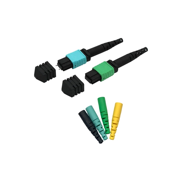
The simplest method: connect two cables pre-connectorized via a coupler (also called an adapter). L' mechanical splice aligns two bare fibers in a plastic casing filled with index gel. Fiber optic adapters, also known as couplers, play a crucial role in fiber optic networks by providing a connection point between two fiber optic connectors. They enable seamless and reliable optical signal transmission between different fiber optic cables, connectors, or devices. In this tutorial. This tab provides a brief explanation of how we determine several key specifications for our 1x2 couplers. 1x2 couplers are manufactured using the same process as our 2x2 fiber optic couplers, except the second input port is internally terminated using a proprietary method that minimizes back. 📦 For purchasing, use the RP Photonics Buyer's Guide for fiber couplers. It provides an expert-curated supplier directory, buyer-focused technical background information, and structured selection criteria to support professional procurement decisions. What is a Fiber Coupler? Fiber couplers belong. You use optical couplers and splitters to split or join signals in fiber networks. These devices help you control light signals well. For example, optical splitters send light to many output ports. You can also use them to join light from. Three methods for connecting two fiber optic cables: fusion splicing, mechanical coupler, and splicing.
[PDF]
Join Jake from Omnitron in this comprehensive tutorial. Understand the nuances of single-mode and multimode fibers, and how to bridge the gap using media converters. But what happens when you need to connect an existing multi-mode campus network to a new single-mode service provider link? You can't just splice them together. This is where fiber conversion comes in. This guide will break down the professional methods to achieve seamless single-mode to multi-mode. Converting multimode fiber to single-mode fiber can improve network performance and future-proof infrastructure. An essential difference between them lies in the transmission distance they can accommodate.
[PDF]

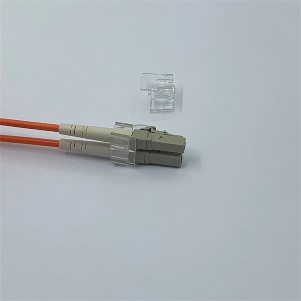
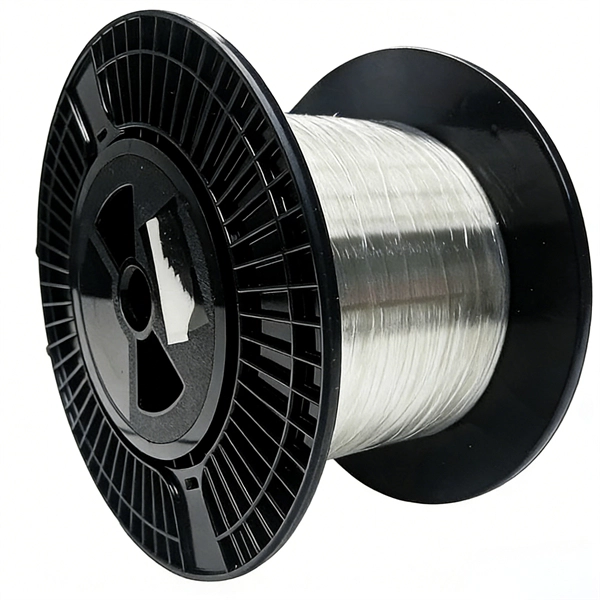
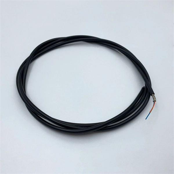
Fiber-optic cables are made by taking an individual fiber or bundle of fibers and adding coating and protective layers. A TOSLINK optical fiber cable with a clear jacket. These cables are used mainly for digital audio connections between devices. A fiber-optic cable, also known as an optical-fiber cable, is an assembly similar to an electrical cable but containing one or more optical fibers that are used to carry. A fiber optic cable consists of five basic components: the core, the cladding, the coating, the strengthening fibers, and the cable jacket. When searching for a fiber optic cable, we need to pay attention not only to the connectors, such as SC to ST fiber cable, LC to SC fiber patch cable, or SC to. Data transfer and telecommunications have been transformed by optical fiber technology. It consists of tiny glass or plastic fibers that can carry data as light pulses. The first low-loss optical fiber was created in 1970 by Robert Maurer, Donald. At its simplest, a fiber optic cable is a hair-thin strand of incredibly pure glass designed to transmit information using light pulses instead of electrical signals. This fundamental difference is why it's so fast and efficient. The process relies on a principle called Total Internal Reflection. The optical fiber transmits the signal, the strength member provides tensile and crush resistance, and the jacket protects the overall cable from the environment. Govind Agrawal, the Dr. Wyant Professor of Optics at the.
[PDF]
PLC optical splitters (planar waveguide optical splitter) is a key component in optical fiber communication networks and is widely used in optical fiber distribution systems such as FTTH (fiber to the home) and PON (passive optical network). PLC (Planar Lightwave Circuit) splitters are crucial components in optical networks, facilitating the distribution of optical signals to multiple destinations. This article provides a comprehensive understanding of PLC splitters, including their working principle, types, advantages, deployment. PLC splitter, also called Planar Waveguide Circuit splitter, is a device used to divide one or two light beams into multiple light beams uniformly or combine multiple light beams to one or two light beams.
[PDF]

Optical fibers are circular dielectric wave-guides that can transport optical energy and information. They have a central core surrounded by a concentric cladding with slightly lower (by ≈ 1%) refractive index. Optical fibers are typically made of silica with index-modifying dopants. An optical fiber, or optical fibre, is a flexible glass or plastic fiber that can transmit light from one end to the other. Such fibers are widely used in fiber-optic communication, where they permit transmission over longer distances and at higher bandwidths (data transfer rates) than. What are fiber optic cables made of? A fiber optic cable consists of five basic components: the core, the cladding, the coating, the strengthening fibers, and the cable jacket. When searching for a fiber optic cable, we need to pay attention not only to the connectors, such as SC to ST fiber cable. Optical fibers are circular dielectric wave-guides used to contain and transmit light over short or long distances. They consist of three elements as shown in Figure 1: a central core, cladding and a protective coating. The five main parts of a fiber optic cable are: Glass: The core component where light travels to carry data. This advanced cabling solution allows fast, secure data transfer and telecom over long distances. And glass optical cables are made from silica, which, in pure form, has a very low loss in infrared region of the optical spectrum. Designed for longer distance, very high-performance data.
[PDF]
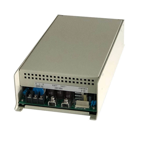
There are hybrid optical and electrical cables that are used in wireless outdoor Fiber To The Antenna (FTTA) applications. In these cables, the optical fibers carry information, and the electrical conductors are used to transmit power. These cables can be placed in several environments to serve antennas mounted on poles, towers, and other structures. According to Telcordia GR-3173, Gener. OverviewA fiber-optic cable, also known as an optical-fiber cable, is an assembly similar to an but containing one or more that are used to carry light. The optical fiber elements are typically individually. Optical fiber consists of a and a layer, selected for due to the difference in the between the two. In practical fibers, the cladding is usually coated wit. In September 2012, NTT Japan demonstrated a single fiber cable that was able to transfer 1 per second (10 bits/s) over a distance of 50 kilometers. Although larger cables are available, the highest stra.
[PDF]
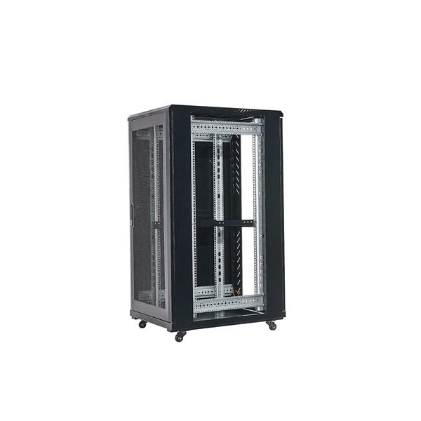
The zinc plating on these tray systems offers good corrosion resistance. Cut, bend, and connect the wire mesh trays to route cable and hose in configurations such as curves, slopes, and tees. They are a ligh.
[PDF]
The bend radius measures how much a cable can be bent before it becomes damaged. Your cable's specifications for this will usually depend on the tensile load applied to it. These measurements will vary.
[PDF]
6Wresearch actively monitors the Barbados Optical Fiber Cables Market and publishes its comprehensive annual report, highlighting emerging trends, growth drivers, revenue analysis, and forecast outlook. Our insights help businesses to make data-backed strategic decisions with. Equipment may be required for some packages & features. Pricing may vary depending on service area. Lifeline or Basic service needed for additional TV packages. Additional equipment may be required. Whether you are a professional or a DIY'er: at Kooyman we'll get you started! From home electronics to energy-efficient air conditioners, we have everything you need to power up your space. Our expertise extends to impeccable electrical finishing and electrical installations, ensuring your home. Barbados' leading IT, Computer & Consumer Electronics Superstore Retailer. From custom-surfaced prescriptions to ready-stock finished lenses, we provide comprehensive solutions for optical professionals. Available in single vision, bifocal, and progressive designs. Ready-to-edge stock lenses for. Moved Permanently. Redirecting to https://cartersonline. bb/electrical/cable-and-accessories/cables. Immerse yourself in a world of unparalleled variety as we offer an extensive array of extraordinary electrical products for your discerning needs. From top-notch outlets.
[PDF]

This paper is focused on the performance analysis of protection mechanisms utilized in common wavelength division multiplexing-based passive optical networks. Wavelength division multiplexers are fundamental to the functioning and performance of integrated photonic circuits, with applications ranging from optical interconnects to sensing and quantum technologies. Current solutions are limited by trade-offs between channel spacing, crosstalk, insertion. Wavelength division multiplexing (WDM) is a technology for increasing the transmission capacity of optical fiber communications by sending multiple data channels simultaneously through a single fiber, each on a different wavelength of light. The main aim of the proposed research is providing an option of comparing different traffic protection scenarios for advanced optical. Herein, an attention-grabbing and up-to-date review related to major multiplexing techniques is presented which includes wavelength division multiplexing (WDM), polarization division multiplexing (PDM), space division multiplexing (SDM), mode division multiplexing (MDM) and orbital angular momentum. The journey of optical multiplexing began in the 1970s with the introduction of Wavelength Division Multiplexing (WDM), which revolutionized the capacity of optical communication systems. The primary objective of optical multiplexing has been to maximize the utilization of available bandwidth in.
[PDF]
Find low everyday prices and buy online for delivery or in-store pick-up. Find low everyday prices and buy online for delivery or in-store pick-up. Shop products from small business brands sold in Amazon's store. Discover more about the small businesses partnering with Amazon and Amazon's commitment to empowering them. Learn more Made with chemicals safer for human health and the environment. Manufactured on farms or in facilities that protect. 20pcs Transmission Type Photoelectric Switch Optical Interrupter Sensor Opto. OPB825 Opto optical switch, photointerrupter. SA-6C Digital Toslink Optical 4x1 Switch with 3ft Optical Cable and IR Remote Contr. Get the best deals on optical switch when you shop the largest online selection at. Shop for Optical switcher at Best Buy. Networx® Gigabit Ethernet Fiber Media Converter - UTP to 1000Base-SX - ST Multimode, 5. Get fast shipping and top-rated customer service. Price when purchased online Cisco IE-4010-16S12P Ethernet Switch - 12 Ports - Manageable - Gigabit Ethernet - 1000Base-X, 10/100/1000Base-T - 3 Layer Supported - Modular - 16 SFP Slots - Optical Fiber, Twisted Pair - 1U - Rac. Live better. The FOSW-1x1 or 1x2 optical switch is based on opto-mechanical technology with proven reliability.
[PDF]