An optical fiber, or optical fibre, is a flexible or plastic that can transmit from one end to the other. Such fibers are widely used in, where they permit transmission over longer distances and at higher (data transfer rates) than electrical cables. Fibers are used instead of metal because signals travel along them with less and are immune to.
[PDF]
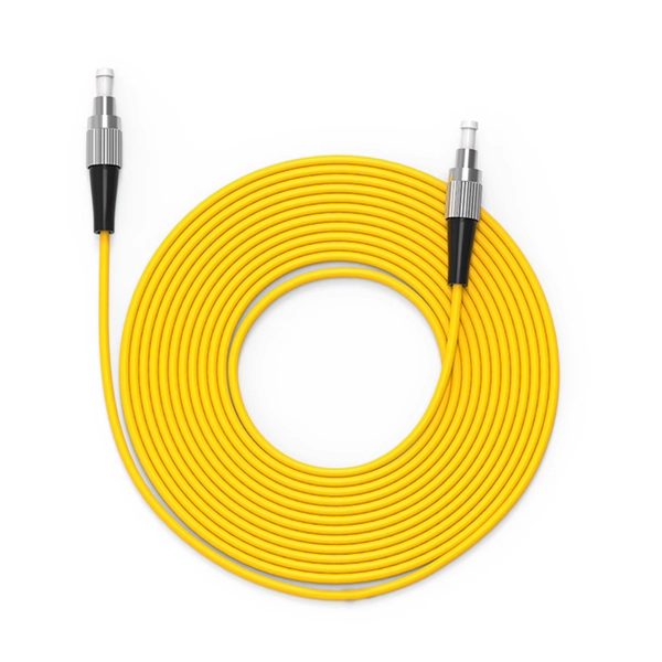
A fiber-optic cable, also known as an optical-fiber cable, is an assembly similar to an but containing one or more that are used to carry light. The optical fiber elements are typically individually coated with plastic layers and contained in a protective tube suitable for the environment where the cable is used. Different types of cable are used for in different applications, for exa.
[PDF]
This guide explains the latest EIA/TIA-598-D fiber color-coding standard used to identify fiber types, inner fiber sequences, and connector polish styles. With clear tables and updated details, it serves as a comprehensive reference for technicians handling modern fiber optic. What is an Optical Cable? Before we dive into the physical appearance of optical cables, let's take a brief look at what they are and how they work. Understanding fiber‑optic color codes is essential for any technician tasked with installing, maintaining, or troubleshooting modern fiber networks. By adopting the TIA/EIA‑598C standard, you gain a universal “language” of colors that speeds identification, reduces miswiring, and enhances safety. Fiber optic color knowledge is crucial for anyone working in telecommunications, networking, or data management. This tiny strand of optical fiber plays a huge role in modern technologies, transferring data at the speed of light. The two main types — Single Mode (SM) and Multimode (MM) — differ in construction, performance, and application.
[PDF]

Our extensive offering of fiber optic cables, connectors, cassettes, enclosures, patch cords, cable assemblies, cable distribution products and accessories deliver high performance, reliability, and scalability. Precision Fiber Products, Inc. offers a wide range of fiber optic products. We specialize in fiber optic interconnect components, including fiber optic cables, connectors, cable splicing, ferrules, and more. Ready to get started? Get a quote now! In just a few steps, you can receive a quote. ESTABLISHED IN 1976: Selected three times as an "INC 500" company. Designated as one of the "Hottest VAR/Distributors". Delivering high performance, reliability, and scalability, the Base-16 Fiber Cabling. Belden's extensive line of indoor and outdoor cable products is offered in tight buffer and loose tube designs. Armored, burial, and ruggedized designs are suited to a host of industrial environments. For each product design, items for OM1, OM3, OM4, OM5, and OS2 (Singlemode) items have been. Cables. com (Datacomm Cables, Inc. ), is headquartered in Long Island, New York (Deer Park, NY). Since 2001, Datacomm Cables has been a single source offiber optic cables,networking cables,power cords,crypto cables, datacenter cables,Cat5 cables,Cat6 cable,Cat6A cable,shielded cables,outdoor cables.
[PDF]

The machine is a hand-held free-to-height cable quick-attachment tool with internal components such as controllers that automatically complete all steps of cable tying. It can be widely used in the high-altitude operation in the field of communication engineering and is. Power Source: Rechargeable lithium battery Bundling range: 0-60mm Binding : can binding 1600 times for one time fully charger. Voltage: 12V Battery: 7800 mAh/group, Fully charged, one battery can work more than 1600 times, about 3 kilometers or more Battery installation mode: external and embedded. Delivery time is estimated using our proprietary method which is based on the buyer's proximity to the item location, the shipping service selected, the seller's shipping history, and other factors. Delivery times may vary, especially during peak periods. Buyer pays for return. Buy Newly Designed Second Generation High Altitude Optical Fiber Cable Bundling Machine for Efficient Network Installation at Aliexpress for. Find more 1420, 153713 and 1537 products. Enjoy ✓Free Shipping Worldwide! ✓Limited Time Sale ✓Easy Return. Maximum order quantity: 1 piece Customized logo (+ from /Min.
[PDF]
from outside the US. EMEA Specific: +49 (0) 228 7489 201 HCS and GiHCS are registered tradema time without notice. This document is for informational purposes only and is not intended to modify or supplement any OFS warranties or specifications relating to any of its. from outside the US. STFOC uses our patented cable jacket construction designed to protect the fiber in the harsh subsea environment. Non-KinkTMSTFOC has a patented design to protect. CommScope bundles hybrid cabling to your custom specifications, using our high-performance fiber-optic, unshielded twisted pair and coaxial cables. Devices deployed at the network edge—a 5G radio, a security camera, or an industrial sensor—require high-speed data connectivity and power. It is technically possible to have a separate fiber and electrical cable, but it adds complexity, cost, and maintenance overhead. Optical hybrid cables address. challenge—OCC has what you need. Our team will make sure the configuration is tailored to your needs and will provide a detailed quote. Email us using the Request a Quote below, or give our team a call. Drive, Avon, CT 0600 erat ing Bend Radiu erat ing Bend Radius Cons from outside the US. Teledyne ODI ofers a comprehensive line of fiber optic and electro/optic hybrid wet mate interconnect products. Wet mate connectors are available in ROV Mate, Stab Mate and Manual Mate configurati sm.
[PDF]

The optical power meter is similar to the voltohmmeter in application but measures the optical resistance (losses measured in dBm or dBM) of a cable before and after installation and provides a comparative analysis of the splices. The range of the meter is adjustable. Regularly testing fiber optic cables helps minimize network downtime, lengthens the network's longevity, reduces maintenance requirements, and helps support network reconfiguration and upgrades. These factors significantly add to the fiber optic network's long-term performance, manageability, and. Several types of tests are commonly conducted to assess and maintain the health of fiber optic networks. Continuity testing verifies that the fiber is intact and that light can pass through from one end to the other without any blockages. These test procedures assess the physical and functional qualities of fiber optic cables, connectors, and the network as a whole. Key tests include: Effective fiber testing utilizes advanced tools such as Optical. One way to test a splice is to use an Optical Power Meter. As the components like fiber, connectors, splices, LED or laser sources, detectors and receivers are being developed, testing confirms their performance specifications and helps. Regular testing of fiber optic cables is not just a preventive measure; it's an investment in the longevity and efficiency of your network. By identifying potential issues early, you can enhance.
[PDF]
In this informative guide, we'll walk you through the step-by-step process of stripping and preparing fibre optic cable for termination, covering techniques, tools, and best practices to help you achieve successful terminations in your fibre optic installations. Strip the jacket and buffer: Using a fiber optic cable stripper, remove the outer jacket and buffer tubes from the cable. Make sure to strip the appropriate length, as specified by the manufacturer. Be cautious not to damage the fibers during this process. Cleave and cut the fibers: After. In this instructional video, Bob Licari, Test Equipment Product Manager, demonstrates a simple way to strip optical fiber. more Audio tracks for some languages were automatically generated. Eventually, this imperfection can initiate a crack when the. It is impossible to work in fiber optics without having a good working knowledge about cables and skills in pulling, placing and preparing cables for termination and splicing. Properly stripping the cable and preparing the fibre ends ensures a clean and secure connection, leading to optimal signal transmission and network performance. Terminating fiber optic cables essentially means putting connectors on fiber optic cable so that you can connect the cable to various devices or network components. Think of it as the equivalent of connecting the dots in a complex puzzle; without proper termination, the whole system can break down.
[PDF]
In this comprehensive guide, we delve into the intricacies of fiber optic splicing—encompassing methodologies, instruments, and best practices—while highlighting Dekam Fiber's state-of-the-art offerings that facilitate durable networks. It's the process of joining two fiber optic cables using techniques such as fusion splicing and mechanical splicing, crucial for maintaining uninterrupted communication networks. In this guide, we'll explore what splicing of fiber entails, why it's important, and dive into the key methods and tools. Fiber termination refers to the process of preparing the end of a fiber optic cable to connect to another fiber, a device, or a network. Proper termination is essential for ensuring optimal performance, reducing signal loss, and maintaining the durability of the connection. Unlike using connectors, which are designed for frequent connection and disconnection at patch panels, splicing creates a permanent, stable joint with minimal light loss. What is Fiber Optic Splicing and Why is it Needed? – #1. Use and Maintain Your. Splicing fiber optic cables involves precisely joining two fiber ends to create a continuous optical path. This article explores how to splice fiber, focusing on achieving minimal signal loss and ensuring reliable data transmission through the proper fusion splicing techniques and mechanical.
[PDF]

Recommendation ITU-T L. 101 describes characteristics, construction and test methods of optical fibre cables for buried application. 0, in February 2016. First, in order to demonstrate sufficient performance of an. ion) and “ Installed” (after installation). The following formulas may be used to determine general guidelines for installing Corning Optical Communications fiber optic cable; however, refer to the cable specifi simply double the minimum working bend radius. Split cable guides and split 40-in. 1. The methods described are intended for guideline use only, as it is impossible to cover all the various conditions that may arise during an installation. Individual. The Fiber Optic Association, Inc. (FOA) was founded in 1995 to help develop the workforce to build the fiber optic networks to support a rapid expansion in communications and the Internet. The charter of the FOA was to promote professionalism in fiber optics through education, certification, and. Home / Instruction Sheets / Fiber Optic Cable Direct Burial Guidelines Need Help?. When planning a fiber optic network installation, one of the most common questions is: How deep are fiber optic cables buried? Proper burial depth is critical for the safety, durability, and performance of your communication infrastructure.
[PDF]

Recommendation ITU-T L. 101 describes characteristics, construction and test methods of optical fibre cables for buried application. 0, in February 2016. The short answer, based on general industry standards and the National Electrical Code (NEC), is that fiber optic cable is typically buried between 24 inches (60 cm) and 30 inches (76 cm) deep. However, simply hitting this depth isn't enough to guarantee your network survives. Factors like the. Underground fiber optic cable installation follows specific standards that govern burial depth, testing methods, installation techniques, and safety requirements. 5 is an article in the National Electrical Code that addresses requirements for underground electrical installations, including minimum cover requirements—the measurement used to determine the distance from the top of an underground cable or raceway to the finished grade. 5. Estimate minimum burial depth (cover) for underground electrical, fiber, and low-voltage cable runs using a practical, code-aware ruleset. Use this page to plan trench depth, compare conduit options, and prepare for inspection conversations. Use this calculator to estimate a minimum burial depth. Recommendation ITU-T L. This depth is generally considered the absolute shallowest for any telecommunications cable that is not placed.
[PDF]

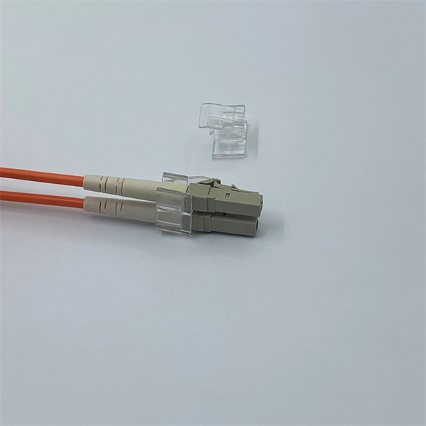
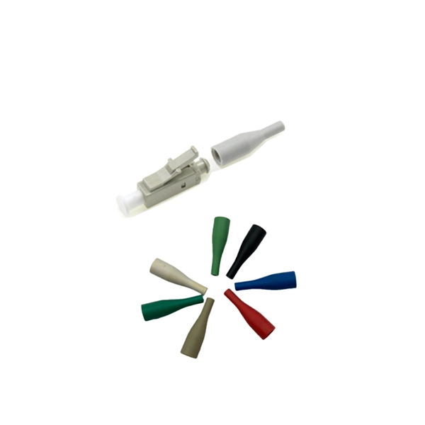
In this guide, we'll walk you through the entire process of preparing fiber optic cable for splicing and termination to fiber connectors. We'll explore the necessary tools, safety precautions, and step-by-step procedures for cable connectors, mechanical and fusion. At the heart of any robust fiber optic network lies a crucial process: Preparing a fiber cable for termination of a connector or splice. Two types of splices are used in fiber optic cabling one is Mechanical the other is Fusion. Whether you're installing a new network, expanding an existing one, or. Splicing fiber optic cable is an extremely important phase for making dependable, high-speed communication infrastructures. Regardless of the type of fiber network you're deploying, be it for telecom, enterprise data centers, or smart city infrastructure, fusion splicing provides the benefits of. Think of a fiber optic cable splice as the seamless stitching that keeps data flowing through the delicate threads of a network—like a master tailor joining fabric with precision. This article explains when. We terminate fiber optic cable two ways - with connectors that can mate two fibers to create a temporary joint and/or connect the fiber to a piece of network gear or with splices which create a permanent joint between the two fibers. These terminations must be of the right style, installed in a. So in essence, fiber optic splicing is a process used to join two separate fiber optic cables together.
[PDF]

In this step-by-step tutorial, we show you exactly how to place a fusion splice safely and securely inside a Coyote fiber optic splice enclosure. Fiber cable splicing is a critical step in building reliable fiber optic networks. Whether in data centers, telecom rooms, or outdoor FTTx deployments, proper splicing inside a fiber enclosure ensures low signal loss, long-term stability, and easy maintenance. This guide explains what fiber cable. Think of a fiber optic cable splice as the seamless stitching that keeps data flowing through the delicate threads of a network—like a master tailor joining fabric with precision. Whether repairing a broken cable or extending a fiber run, fiber optic splicing ensures light signals travel. In addition to the outer skin of the optical cable (if any, please remove the shielding and armoring) and then remove each wrapping layer until the loose tube is exposed. Make sure you read and understand this instruction as well as instructions provided with related assemblies before. In this guide, we cover the basics of fiber optic splicing, how to perform splicing using two different methods, and finally some best practices to perform good fiber splicing. What is Fiber Optic Splicing and Why is it Needed? – #1. Use and Maintain Your.
[PDF]