
In this guide, we'll walk you through the entire process of preparing fiber optic cable for splicing and termination to fiber connectors. We'll explore the necessary tools, safety precautions, and step-by-step procedures for cable connectors, mechanical and fusion. At the heart of any robust fiber optic network lies a crucial process: Preparing a fiber cable for termination of a connector or splice. Two types of splices are used in fiber optic cabling one is Mechanical the other is Fusion. Whether you're installing a new network, expanding an existing one, or. Splicing fiber optic cable is an extremely important phase for making dependable, high-speed communication infrastructures. Regardless of the type of fiber network you're deploying, be it for telecom, enterprise data centers, or smart city infrastructure, fusion splicing provides the benefits of. Think of a fiber optic cable splice as the seamless stitching that keeps data flowing through the delicate threads of a network—like a master tailor joining fabric with precision. This article explains when. We terminate fiber optic cable two ways - with connectors that can mate two fibers to create a temporary joint and/or connect the fiber to a piece of network gear or with splices which create a permanent joint between the two fibers. These terminations must be of the right style, installed in a. So in essence, fiber optic splicing is a process used to join two separate fiber optic cables together.
[PDF]

Mainly 9steps: Step 1: cut cable with cutting machines in lengths Step 2: put the connector spare parts on the cable Step 3: Strip cable jacket, coating till bare fiber, and make all parts in ready Step 4: Insert fiber into ferrule, glue dispenser and heat oven Step 5:. Mainly 9steps: Step 1: cut cable with cutting machines in lengths Step 2: put the connector spare parts on the cable Step 3: Strip cable jacket, coating till bare fiber, and make all parts in ready Step 4: Insert fiber into ferrule, glue dispenser and heat oven Step 5:. Learn how to make a fiber optic patch cord step by step, from preparation to testing, for reliable high-performance connections. Most guides on making fiber optic patch cord 1 s feel incomplete. They often focus on the final assembly steps, leaving the foundational stages a mystery. From cable cutting to connector assembly and testing, you will gain valuable insights into the production of. Fiber optic patch cords and Pigtails are very important passive fiber optic components in fiber optic networks. Use the fiber optic cleaver to cut the. This document describes the installation and use of the mode-conditioning patch cords listed in Table 1. A mode-conditioning patch cord is shown in Figure 1 IEEE 802. 3z-compliant optical fiber assembly consisting of a single-mode fiber permanently coupled off-center to a 62. 5-micron multimode.
[PDF]
It's important to watch the supply reel while installing to ensure the minimum bend radius isn't compromised. Use proper cable pulling lubricants. Sequentially mark the pulling role for easy identification. Use extreme caution when removing the pull eye. Fiber optic cable is surprisingly strong, durable and pliable; however, several best practices should be followed to ensure a successful cable installation. This article explores recommendations for pulling and installing fiber optic cable. Most fiber optic cables boast a pull strength of 100 – 200. That's where investing in high-quality patch cords makes a real difference—they arrive with better polishing, protection caps, and lower insertion loss, reducing the margin for error during deployment. When discussing installation mistakes, endface contamination deserves special attention because. Fiber optic troubleshooting is an essential skill for network administrators, technicians, and engineers responsible for maintaining and repairing fiber optic systems. These high-speed, high-capacity communication networks are increasingly replacing copper cables, offering superior performance and. Harnessing the full potential of fiber optics hinges greatly on the quality of its installation. During installation, all curvatures should be smooth. The cable should be bent as little as possible. Most fiber damage does not come from normal operation after the system is live.
[PDF]
You use optical couplers and splitters to split or join signals in fiber networks. These devices help you control light signals well. For example, optical splitters send light to many output ports. A fiber optic splitter is a passive optical component that divides a single incoming optical signal into two or more outgoing signals, or combines multiple incoming signals into one. Unlike active devices (which require power), splitters operate without electricity, relying solely on the physics of. Fiber optic cables consist of thin strands of glass or plastic fibers that transmit data as light signals. Each fiber is composed of a core, cladding, and a protective outer coating. The core is where light travels, while the cladding reflects light back into the core to minimize signal loss. The. Fiber optics, a cornerstone of modern telecommunications, relies on transmitting data through light signals within fiber optic cables. You can also use them to join light from. A fiber broadband provider typically determines and overall split ratio for the network, such as 1x32 or 1x64, and uses combinations of splitters to meet that ratio with each PON port. 1x32 splits were common in North America for G-PON architectures. These fibers transmit data as light signals, which are converted into electrical signals at the receiving end. The benefits of optical cables are numerous.
[PDF]
This guide walks you through the complete fiber installation process, from checking availability to optimizing your Wi-Fi network performance. Upgrading to fibre internet involves replacing your existing copper cables with new fibre-optic ones. This upgrade brings faster speeds and more reliable connectivity. Here is what the installation process is like: One of our technicians will visit your home, remove the old copper wiring and. If you need Fiber Optic Cable Installation in Malta or areas close by allow us to assist you by connecting you with specialized pros who can do the work you request. Step 1: Planning Before any installation begins, thorough planning is essential. This includes determining the network's requirements, such as bandwidth, distance, and the number of. This guide will explain the entire set of activities involved in installing Fiber optic cable contractors -from the early planning stage right through testing-for facility managers, IT teams, and low-voltage contractors to build high-performance networks safely and efficiently. The processes. The Fiber Optic Association, Inc. (FOA) was founded in 1995 to help develop the workforce to build the fiber optic networks to support a rapid expansion in communications and the Internet. The charter of the FOA was to promote professionalism in fiber optics through education, certification, and. We offer :- For more information email us on sales@merlin.
[PDF]
On average, commercial projects range from $5,000 to $20,000 per mile underground and $40,000 to $60,000 per mile for aerial deployment. Individual business connections often cost between $15,000 and $30,000 for 100–200 network drops. Buying fiber optic installation services involves several cost components, with total price influenced by length, location, and access. The main cost drivers include trenching or aerial deployment, materials, labor hours, and any required permits. This guide presents typical price ranges in USD to. The initial cost of installing fiber optic cables can vary depending on the chosen installation method and specific project requirements. In preparing this second edition of the Fiber Deployment Cost report, Cartesian gathered inputs from a wide variety of firms building. Getting accurate cost estimates is crucial for winning fiber installation bids. Smart contractors know that underground vs aerial installation pricing varies wildly based on location and project conditions. This breakdown gives you real numbers to build better estimates. We'll show actual costs for. Home and business buyers typically see a wide range of costs for fiber optic projects, driven by distance, fiber type, conduit needs, and labor. The price can shift based on underground vs. aerial routes, equipment choices, and whether new permits are required. Some variables are less determinate.
[PDF]

A massive outage has been reported in the Los Angeles area on Father's Day after internet and cable provider Spectrum linked the issue to "criminal acts of vandalism. " "We are currently working on a Fiber cut affecting the Los Angeles area. We are sorry for the inconvenience this. SPARTANBURG COUNTY, S. (WSPA) – Spectrum is offering $25,000 for information leading to the arrest of a suspect accused of cutting and damaging cable lines. Officials said a fiber optic line was intentionally cut, resulting in temporary outages in parts of Spartanburg County, including Inman. Authorities in Spartanburg County, South Carolina, are searching for a vandal who they say cut fiber optic lines Sunday morning. Spectrum says the lines were intentionally cut, resulting in a temporary outage for residents and businesses. In a statement, a Spectrum spokesperson writes, "Criminal. ©2025 NewsBreak. The incident is being treated as an attempted theft. 'The Free Press' reporter Madeleine Rowley discusses the reality behind President Biden's broadband internet project on 'The Bottom Line. Domestic Violent Extremists (DVEs) have increasingly discussed targeting. Several Spectrum lines cut and laid out as repairs continue to restore services throughout the Long Beach area in Signal Hill Thursday, June 19, 2025. Photo courtesy of Spectrum. An internet outage across large parts of Long Beach was caused by someone who intentionally cut fiber optic lines “in a.
[PDF]

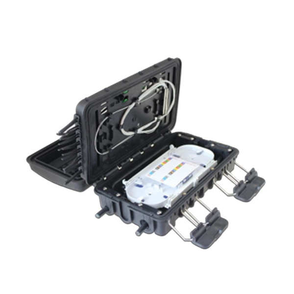
In this step-by-step tutorial, learn how to splice fiber optic cables like a pro — perfect for telecom technicians, network engineers, and field techs. more 🔧 Watch a real-time fiber optic splicing demo in action!. Fiber cable splicing is a critical step in building reliable fiber optic networks. Whether in data centers, telecom rooms, or outdoor FTTx deployments, proper splicing inside a fiber enclosure ensures low signal loss, long-term stability, and easy maintenance. This guide explains what fiber cable. In this guide, we cover the basics of fiber optic splicing, how to perform splicing using two different methods, and finally some best practices to perform good fiber splicing. What is Fiber Optic Splicing and Why is it Needed? – #1. Whether repairing a broken cable or extending a fiber run, fiber optic splicing ensures light signals travel. Regardless of your level of experience, creating high-quality, high-performance fiber optic networks requires developing your skills in fusion splicing. This guide reveals the secrets to fusion splicing with little fluff—just proven, straightforward techniques refined from years of work in the.
[PDF]

Fiber optic network design (896. 83 KB). Welcome to the Corning LANscape® Solutions Product Drawings Resource Center, your complete source for our optical hardware component drawings. The two-dimensional and isometric hardware products drawings are available in PDF (Adobe® Acrobat®), DXF (AutoCAD®), VSS (Visio® Stencil) formats, and. I'm wanting to create documentation for a control fiber optic network. I'm needing symbols for common fiber optic components, cables, connectors, backbone ports, etc. Can anyone help me out? Some examples of a diagram would also help. 10-27-2018 01:41 AM Do you know if there's some symbol standard. Search by part number or description such as CAT5, CAT6, OSP, etc. Sort by any of the table headers. Use the drop down menu to filter by product category and type. Sort by any. Download CAD block in DWG. Free CAD and BIM blocks library - content for AutoCAD, AutoCAD LT, Revit, Inventor, Fusion 360 and other 2D and 3D CAD applications by Autodesk. CAD blocks and files can be downloaded in the formats DWG, RFA, IPT, F3D. You can exchange useful blocks and symbols with other CAD and BIM users.
[PDF]

When it comes to testing fiber optic cables, a Visual Fault Locator (VFL) is an essential tool in your toolkit. A VFL is used to detect faults, breaks, or bends in fiber optic cables by emitting a bright red light that is visible even through the fiber's jacket. It's a cost-effective and. A Visual Fault Locator which can be also called visual fault identifier (VFI), fiber fault locator, fiber fault detector, etc., is a visible red laser light designed to inject visible red light energy into an optical fiber. Using a VFL to diagnose issues can save time and cost when diagnosing an. A visual fault locator is a compact, handheld device that emits a visible light beam, typically in the red wavelength range, through a fiber optic cable. It works by injecting a visible red laser light into the fiber, which can be seen through the jacket or at the end of the cable. If the light doesn't come out the other side, there might be a problem. You. And in the end we will show you how to use an old cell phone's camera to detect light in a fiber optic system. It uses a bright incandescent bulb or visible LED source to.
[PDF]
In this guide, we'll break down the essentials, explore different wiring configurations, and provide you with practical tips to get your sensors up and running smoothly. So, grab your tools, and let's get started! Before we jump into wiring diagrams, let's quickly recap what fiber optic sensors are. working principle: Fiber optic sensors use the propagation characteristics of light to detect or measure various physical and chemical quantities. Here are some basic working principles of fiber optic sensors: Propagation of Light: An optical fiber consists of two parts: a core (the central part of. A Fiber Sensor is a type of Photoelectric Sensor that enables detection of objects in narrow locations by transmitting light from a Fiber Amplifier Unit with a Fiber Unit. Detection in Narrow Locations The small sensing section and flexible Fiber Unit cable enable a Fiber Sensor to. Click to download the ODiSI Fiber Optic Sensor Installation Guide. The following instructional videos explain how to install, configure, and calibrate the FiberPatrol FP400 fiber optic fence-mounted intrusion detection sensor. Copyright © 2026 Senstar Corporation. Legal | Accessibility. Surprisingly Stable Detection with Your Finger tip. Exceptionally easy operation and stabilizing technology reduce maintenance cost. If you Login / Signup, you can download the PDF of the Manual. Please note some product models not sold in Singapore may be included in the following manual (s) for.
[PDF]

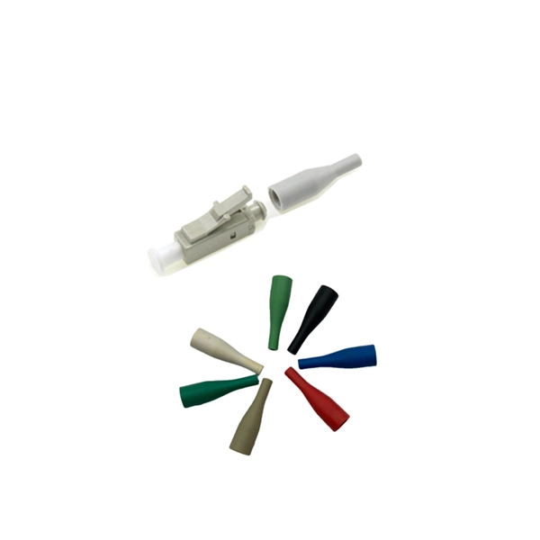
pigtails can be divided into single-mode (colored yellow) and multimode (colored orange) fiber. Multimode pigtails use 62.5/125 micron or 50/125 micron bulk multimode fiber cables and terminated them with multimode fiber optic c. pigtails can be divided into single-mode (colored yellow) and multimode (colored orange) fiber. Multimode pigtails use 62.5/125 micron or 50/125 micron bulk multimode fiber cables and terminated them with multimode fiber optic connectors at one end. 10G multimode fiber cables (OM3 or OM4) are also available in optic pigtails. The jacket color of 10. Fiber Optic Pigtails, In fiber optic cable installation, how cables are attached to the system is vital to the success of network. If done properly, optical signals would pass through the link with low attenuation and little return loss. pigtail offers an optimal way to joint optical fiber, which is used in 99% of single-mode applications. This pos. According to different types of pigtail cable connector terminated at the end, there are LC fiber pigtail, SC pigtail, ST pigtail, FC pigtail, fiber pigtail and so on. With different structures and appearance, each of them has their own advantages in different applications and systems. Let's go through some widely used ones. SC Pigtail: SC pigtail.
[PDF]
No, single-mode SFPs are designed to work with single-mode fiber cables and multimode SFPs are designed to work with multimode fiber cables. Attempting to use a single-mode SFP with a multimode fiber cable could result in poor network performance or data transmission errors. It utilizes ultra-low optical attenuation for medium to long transmission. The single mode SFP generally uses high-cost FP and DFB lasers with long wavelengths to optimize. Single-mode (SMF) and multi-mode fiber (MMF) use different core sizes, sources and wavelengths. Understanding the compatibility constraints prevents costly downtime and troubleshooting. To address this question, it's important to understand the characteristics of both single-mode and multimode fiber optics, as well as the implications. Multimode fiber (MMF) uses a larger core diameter (typically 50 or 62. 5 microns) allowing multiple light modes to propagate, suitable for short distances. In contrast, single mode fiber (SMF) has a smaller core diameter (~9 microns) supporting one mode of light, enabling longer reach with minimal. SFP modules are compact, hot-swappable devices used in networking equipment to facilitate the connection of fiber optic cables. They come in two primary types: single-mode and multimode. Single-mode SFPs are designed for long-distance communication, typically using a laser as the light source, and.
[PDF]