Have all of our in-stock product information and specifications right at your fingertips in digital PDF format. is a world class manufacturer of electronic wire and cable, both copper and fiber optic cable. Because of NATIONAL's service attributes and extensive cable manufacturing abilities, we offer a unique set of brand attributes: personalized service and product selection. You can get just about any. DOWNLOAD the Complete Catalog (PDF format 3. 9 MB) Download part numbers, descriptions and specifications of National Wire in-stock products by specific category or download the entire catalog. Heavy-Duty Flexible PVC Insulation – Crack-resistant and built for long-term durability. Versatile Use – Perfect for automotive, solar wiring, LED lighting, home projects, and RV systems. Guaranteed for. Fill out the form with your project details, and we'll help you every step of the way. Feedback! Don't miss out on anything, subscribe to our Newsletter! NNC © Copyright 2009 - 2026. Forgot your password?. Important! LANshack offers premium fiber optic cable & copper wire assemblies. We have all the components to optimize & install your network!. welcome to taobao purchase national standard soft copper wire 25 square millimeters 16 square millimeters copper core cable high-volume building welding machine welding wire welding machine welding machine welding soft copper wire.
[PDF]
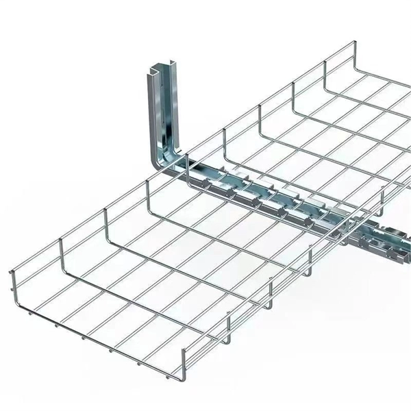
When designing a cable tray wiring system, the designer should evaluate the National Electrical Code's (NEC) Equipment Grounding Conductor (EGC) options that are applicable for the project. Use the cable tray as the EGC. The metal in cable trays may be used as the EGC as per the limitations. Cable tray grounding wire is the safety connection that links your electrical system's cable tray to the ground. This provides a safe path for any stray electrical currents to flow safely into the earth, avoiding damage to your equipment and reducing the risk of electric shocks. It involves connecting cable trays to the facility's grounding system, providing a low-impedance path for fault currents and protecting personnel.
[PDF]
In this comprehensive guide, we'll walk through the best practices for installing various types of fiber optic cable, from patch cords to distribution fiber, and provide practical tips to ensure a successful installation. This article will guide you through the necessary tools, materials, and methods on how to connect fiber optic cables effectively, ensuring you achieve optimal performance from your fiber optic network. Have a network installation project? Fiber Optic Cables: The primary medium for your connections. Fiber optic cable is a type of cable that contains one or more optical fibers—thin, flexible strands of glass or plastic that are designed to transmit light signals. These cables are used for transmitting data over long distances with high bandwidth and low signal loss. Before connecting any fiber cable, you need to assemble the proper preparation tools: With the right tools in hand, follow these key steps to achieve reliable fiber connections: 1. The number one cause of signal loss in optical fiber installations is dirt on. In this video, we'll guide you through preparing and terminating fiber optic cables using SimplyFiber products, known for their high quality, ease of use, and reliability. more Audio tracks for some languages were automatically generated. Why Opt for Fiber Optics? Fiber optic cables have skyrocketed in.
[PDF]
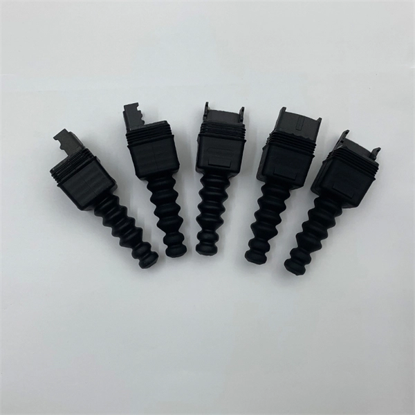
Flex electrical cable, often referred to as flexible cable or flex, is a type of wire that is designed to withstand repetitive bending and movement without damage. Article 400 covers the general requirements and applications for flexible cords as contained in Table 400. A “flexible cord” is two or more insulated conductors enclosed in a flexible covering. Figure 01 The NEC does not. What is a flexible cable? Flexible cables are cables that have multiple conductors (Class 5 or Class 6 conductors) that form the conductor and are insulated and sheathed in a lightweight, flexible material (usually plastic or rubber). Why choose flexible cables for domestic use? It is suitable for. These include flat flexible cable (FFC), stranded wire, power cables, control cables, and flexible electrical conduit. Each type meets specific needs across industries like automotive, electronics, and medical devices. Here is a quick look at how leading cable types are used worldwide: You can. Power distribution cables present a unique challenge to electrical wire interconnect system engineers. Unlike rigid electrical wiring, which is designed for static installations within buildings, walls, or. In any electrical system—whether powering lights in homes, machinery in factories, or robots in operation—cables are the unsung heroes, safely and reliably transmitting electrical energy. As the backbone of power distribution systems, cables connect power sources (such as circuit breakers) to.
[PDF]
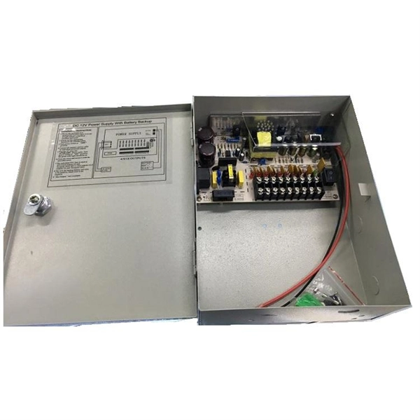
This video shows real on-site footage of electrical installation, demonstrating safe and standardized wiring methods used by professionals. more Learn how to wire a distribution box step by step! This video shows real on-site footage of. Material preparation: Prepare the required circuit breakers, wires, wiring ties and other materials, and ensure that they meet the design drawings and installation requirements. Location determination: Determine the installation position of the circuit breaker according to the position of the. Learn how to install a distribution box safely and correctly. Covers wiring, placement, standards, and expert tips for a compliant setup. A distribution box is the heart of any electrical system. It takes the incoming power and safely distributes it to different circuits throughout your building. It serves as a central hub for distributing electricity throughout a building, ensuring that power is delivered safely and efficiently to all the required locations. This video highlights the installation process for CANTEX Exposed Weatherproof PVC electrical boxes. When an electrical connection is needed outside of a home, commercial or industrial building---or anywhere it might be exposed to the elements, weatherproof electrical boxes and covers are required. It has three categories: residential, commercial and industrial electrical distribution boxes, all of which play important roles in their respective electrical.
[PDF]
This guide summarizes field-proven rules for AI/AO/DI/DO wiring, shows how to choose between NO/NC contacts under the fail-safe principle, and explains how to decode typical cable schedule entries. Instrument installation with the associated cable installation/electrical signal and control wiring should be carried out by skilled personnel who are acquainted with the safety requirements and regulations for the plant site for that specific project. Generally instrument cabling is usually run in. Few factors are to be considered or taken care of while wiring a field instrument to control panel. Based on noise susceptibility limits (NSL) according to IEEE 815 standard, various field instrument signals are classified as below. Noise Susceptibility Limit Grounding of the signal cable Type of cable Cable Terminations Based on noise susceptibility limits (NSL). Note how the hoop-shaped “jumper” wires are all cut to (nearly) the same length, and how each of the wire labels is oriented such that the printing is easy to read: This next photograph shows a great way to terminate multi-conductor signal cable to terminal blocks. Each of the pairs was twisted. A well-designed and properly installed instrument junction box is crucial for the efficient operation and maintenance of electrical systems. Level 1: High to medium susceptibility Level 2: Low susceptibility.
[PDF]

This article provides a detailed technical comparison between fiber optic and copper cables, offering a clear perspective for engineers, network architects, and procurement managers. The core distinction between the two technologies lies in the physics of data. However, the exponential growth in data demand has positioned fiber optic technology as the superior alternative for performance, scalability, and future-readiness., 10G/25G/40G/100G and beyond depending on optics and reach). Copper Ethernet scales too, but practical limits are lower and depend. The two main options are fiber optic cables and copper cables, each with its own advantages and drawbacks. Fiber optic cables are praised for their high performance and scalability, while copper cables remain a cost-effective choice, especially for budget-conscious projects and older systems. Copper wire is more susceptible to interference and has limited data capacity, making optical fiber the preferred choice for modern high-speed. Optical connectivity, utilizing fiber-optic technology, has emerged as the superior choice for modern networking, offering unparalleled performance, reliability, and scalability. For example, a typical 10 Gbps copper Ethernet link (such as Cat 6A) over 100 meters can consume approximately 5 to 8+.
[PDF]

Start by separating your Ethernet cable into two separate cables and connecting them to the back of the Ethernet cable splitter. Once the cables are securely connected, connect the other ends to your desired devices. Ensure that the cables are tightly secure and that all connections. When you need to connect multiple wired devices like computers, printers, and IP phones, but only have one Ethernet wall port, using an Ethernet splitter or network switch can expand your connectivity without rewiring. This guide explains your options and helps you choose the best solution for your. An Ethernet splitter is a small device that allows two Ethernet-connected devices to share a single cable run. It does not increase speed or create extra bandwidth. It simply divides signal pairs. This tool works best in basic setups where running another cable is not possible. An Ethernet splitter. Ethernet cable splitter wiring diagrams are essential for anyone who needs to connect multiple devices in a home or office network. With the ever-increasing popularity of high-speed internet and streaming services, providing reliable connections to multiple devices is becoming increasingly. An Ethernet splitter doesn't actually split a single Ethernet connection to provide separate internet access to two devices. Instead, it utilizes only two of the four pairs of wires within a single Ethernet cable to connect two devices, requiring two splitters for the setup to function correctly.
[PDF]

Attach a ground wire from one of the threaded studs (A) at the bottom of the housing, to the mounting plate (B). The ground resistance between all system parts shall be <. The correct connection method of Distribution box grounding wire mainly includes the following steps: 1. This position is the connection point of the grounding wire in the. The National Electrical Code (NEC) lists eight specific methods to make grounding and bonding connections in Sec. Failure to install these connections properly can result in shock, fire, or, most certainly, power quality problems. Let's take a look at each one in more detail. Listed pressure. Make the most of outdoor spaces with permanent, weathersafe power. Learn our complete installation process from start to finish. Watch our video to learn more. Securing the ground wire: Secure the grounding wire to the ground bar using a grounding screw or terminal. Each DISTRIBUTION BOX and controller must be grounded. On the US market, a 5. 26 mm 2 (10 AWG) ground wire must be used, and in all other markets a 6 mm 2 must be used. Grounding of the units: Attach a ground wire from one of. Learn how to install a distribution box safely and correctly. Covers wiring, placement, standards, and expert tips for a compliant setup. A distribution box is the heart of any electrical system. It takes the incoming power and safely distributes it to different circuits throughout your building.
[PDF]
In this video, we'll walk you through the process of wiring a home distribution box with a detailed connection diagram. Whether you're an electrician or a DIY enthusiast, this guide will help you understand the basics of home electrical distribution. more Welcome to our channel! In this video. An electrical panel box, also known as a breaker box or a distribution board, is a crucial component of any electrical system. It serves as a central hub for distributing electricity throughout a building, ensuring that power is delivered safely and efficiently to all the required locations. What is Distribution Board? Distribution board. Hey, in this article we are going to see the Single Phase Distribution Box Wiring Diagram and Connection Procedure. And all the switching and protective devices are installed in the. Are you ready to master the skill of building electrical panels? This detailed guide provides an excellent base for beginners. Learn about the essential components of panels, such as the circuit breakers and fuses that safeguard against hazards. Then, delve into complex wiring configurations. Single Phase wiring installation is the most common wiring in residential buildings. In Single Phase supply (230V in UK, EU and 120V & 240V in the US & Canada), there are two (one is Line (aka Phase, Hot or Live) and the other one is Neutral) incoming cables from the utility poles to the kWh energy.
[PDF]
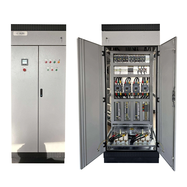
In this video, we'll walk you through the process of wiring a home distribution box with a detailed connection diagram. Whether you're an electrician or a DIY enthusiast, this guide will help you understand the basics of home electrical distribution. more Welcome to our channel! In this video. An electrical panel box, also known as a breaker box or a distribution board, is a crucial component of any electrical system. It serves as a central hub for distributing electricity throughout a building, ensuring that power is delivered safely and efficiently to all the required locations. Distribution Board or DB is an electricity supply system or a common enclosure that distributes the electrical power feed into subcircuits. It includes isolator, RCCB (Residual current circuit breaker) or RCD (Residual-current device) devices, protective fuses or MCB's (Miniature Circuit Breaker). Learn how to install a distribution box safely and correctly. Covers wiring, placement, standards, and expert tips for a compliant setup. It takes the incoming power and safely distributes it to different circuits throughout your building. Box installation: Make sure that Distribution box has been correctly installed and fixed. Material preparation: Prepare the required circuit breakers, wires, wiring ties and other materials, and ensure that they meet the design drawings and installation requirements. To understand how a breaker box works, it is helpful to.
[PDF]
The National Electrical Code (NEC) does not specify the maximum distance for a ground rod from a panel. However, the ground rod should be placed as close as possible to the panel to ensure an effective ground connection. Electrical clearances set the minimum safe distances for panels, overhead lines, pools, and buried wiring — and ignoring them has real consequences. (If these areas are accessible to other than pedestrian traffic, then one of the other conditions applies). Above finished grade or sidewalks, or from any platform or projection from which they. Learn key electrical code requirements for junction boxes, including sizing, grounding, materials, and clearance to ensure safety and efficiency. Whether it's a. The National Electrical Code (NEC) provides comprehensive safety standards for electrical installations, including requirements for electrical panels (main service panels and subpanels or breaker box). NEC Article 408 covers switchboards, switchgear, and Panelboards installation and applications. Following the manufacturer's installation instructions for the ground rod and.
[PDF]

This guide shows you how to organize circuit breaker wiring properly. You will learn to build a safe, efficient, and professional electrical system today. Circuit breaker wiring configurations involve organizing main switches, busbars, and branch breakers within a distribution box. While some homeowners may attempt this, it's highly recommended to hire a qualified, licensed electrician for circuit breaker box wiring. This is a complex and potentially dangerous task that involves working with high voltage electricity. Mistakes can lead to serious injury, fire, or damage to. A breaker box, also known as a circuit breaker panel, is an essential component of any electrical system. It is responsible for distributing electricity throughout a building, ensuring that each circuit receives the proper amount of power. To understand how a breaker box works, it is helpful to. When installing or troubleshooting a power distribution system, understanding how to correctly connect the main electrical supply to the control panel is crucial. The first step involves running a dedicated cable from the incoming supply to the distribution panel, ensuring it is rated for the load. How to read these diagrams. This page contains wiring diagrams for a service panel breaker box and circuit breakers including: 15amp, 20amp, 30amp, and 50amp as well as a GFCI breaker and an isolated ground circuit. Messy distribution boxes are dangerous and very hard to fix.
[PDF]