Secondary-ion mass spectrometry (SIMS) is a technique used to analyze the composition of solid surfaces and thin films by sputtering the surface of the specimen with a focused primary ion beam and collecting and analyzing ejected secondary ions. The mass/charge ratios of these secondary ions are measured with a mass spectrometer to determine the elemental, isotopic, or molecular co. AcronymSIMSClassificationMass spectrometryAnalytesSolid surfaces, thin filmsRelated · HistoryIn 1910, British physicist observed a release of positive ions and neutral atoms from a solid surface induced by ion bombardment. Improved technology in the 1940s enabled the first prototy. A secondary-ion mass spectrometer consists of (1) a primary generating the primary, (2) a primary ion column, accelerating and focusing the beam onto the sample (and in some devices an. for most trace elements are between 10 and 10 atoms per, depending on the type of instrumentation used, the primary ion beam used, the analytical area, and other factors. Samples a. In the field of surface analysis, it is usual to distinguish and dynamic SIMS. Static SIMS is the process involved in surface atomic monolayer analysis, or surface molecular analysis, usually with a pulsed ion.
[PDF]
Explore the precision, applications, and design principles of beam splitters, essential for advancements in scientific research and technology. Beam splitters are integral optical components that divide a beam of light into two or more separate beams. There are two basic types of beamsplitters: Non-polarizing beamsplitters (NPBS): This type of splitter is used to divide (split) a beam into two beams and each output beam is a fraction of the incoming beam regardless of the polarizations. Non-polarizing beamsplitters are used in a variety of. 📦 For purchasing, use the RP Photonics Buyer's Guide for beam splitters. It provides an expert-curated supplier directory, buyer-focused technical background information, and structured selection criteria to support professional procurement decisions. What are Beam Splitters? A beam splitter (or. As a basic and important link in on-chip photon propagation, beam splitting is of great significance for the efficient utilization of sources and the compact integration of optoelectronic devices. It is widely used in power splitting, polarization separation, wavelength division multiplexing and. The SPIE Digital Library offers a wide range of resources on beam splitters, focusing on their design, applications, and performance across various optical systems. The principle of beam splitting is based on the manipulation of light waves using various optical materials and coatings. Their precision and versatility make them.
[PDF]
This occurs because when s-polarized light hits the reflecting surface, the electric field is in the same plane as the surface. The set up is either: Camera lens - beam splitter - camera x2 Or, Beam splitter - (lens + camera) x2 I want to be able to take 2x photos at once, so the light has to go through the beam splitter. I used the polarised flexible sheet as a proof on concept, which worked but need to make it more. A beam splitter or beamsplitter is an optical device that splits a beam of light into a transmitted and a reflected beam. It is a crucial part of many optical experimental and measurement systems, such as interferometers, also finding widespread application in fibre optic telecommunications. Additionally, beamsplitters can be used in reverse to combine two different beams into a single one. The resulting beams are directed along different paths, allowing a single light. 📦 For purchasing, use the RP Photonics Buyer's Guide for beam splitters. It provides an expert-curated supplier directory, buyer-focused technical background information, and structured selection criteria to support professional procurement decisions. What are Beam Splitters? A beam splitter (or. am Splitters/Combiners. This document describes this product line, as well as general operation guidel into two output beams t beams of equal power. The standard product is designed for use in the visible spectrum 400-700 nm wavelength). The cube can only be effectively used as a splitter; used.
[PDF]
Beamsplitter coatings are specialized optical coatings applied to glass or other substrates to split incident light into two or more separate beams, typically by reflecting a portion of the light while transmitting the remainder. Beamsplitters are common components in laser or illumination systems. Beamsplitters are also ideal for fluorescence applications, optical interferometry, or life science or semiconductor instrumentation. Light. Thorlabs offers a wide range of optical beamsplitters. Our plate beamsplitters have a coated front surface that determines the beam splitting ratio while the back surface is wedged and AR coated in order to minimize ghosting and interference effects. Pellicle beamsplitters provide excellent. My question is, does anyone have any idea where to source normal hard coated beam splitter glass I could replace this one with? Or is there a film that can be applied to it? It's just a flat piece of glass that has the half silvered coating on it. This is quite common on Kalart. An Optical Beamsplitter is an optic or optical device that is used to split a beam of light in two. It is a crucial part of many optical experimental and measurement systems, such as interferometers, also finding widespread application in fibre optic telecommunications. This precise ability to split light by wavelength makes beam splitters essential in various fields, including laser systems, semiconductor.
[PDF]
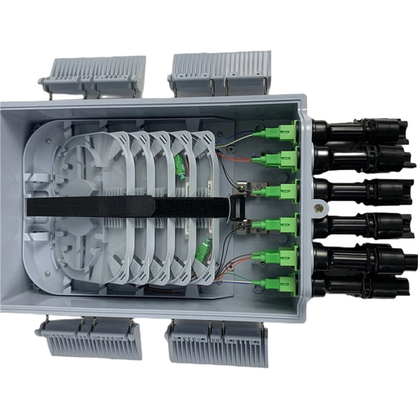
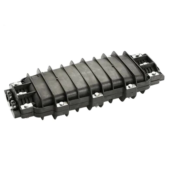
A fiber-optic splitter, also known as a, is based on a of an integrated waveguide power distribution device, similar to a The system uses an optical signal coupled to the branch distribution. The splitter is one of the most important in the link. It is an optical fiber tandem device with many input and output terminals, especially applicable to a passive optical network (,,,.
[PDF]
High-quality 16-way fiber optic splitter with SC/APC interface for FTTH & FTTX deployments. Available starting from $12. 78 per unit, with a minimum order of 1 piece available for wholesale. Indoor 5-1000 MHz Splitter The SDS-16 is a 16-way indoor splitter with a range of 5-1000 MHz. It is finished with a solder back and provides an RFI of -120 dB. Key Features © Blonder Tongue LLC. Range. Blonder Tongue SMR-1600 16-Port Rack Mountable Multi Switch Tested! Get the best deals for 16 Way TV Splitter at eBay. We have a great online selection at the lowest prices with Fast & Free shipping on many items!. Check each product page for other buying options. Need help?. A 16-way splitter is a signal or power distribution device that takes a single input and divides it evenly across 16 output channels. These splitters are essential in various industries, including telecommunications, home entertainment, networking, and audio systems. The type of splitter used. SDS series splitters are available in 12 and 16 way models and are in a zinc die-cast solder back housing for superior performance. They also offer -120 dB RFI. They. Item is Available for immediate shipping from our warehouse. Have any questions? Talk with us directly using LiveChat.
[PDF]
We present an extensive study of an ultra-compact grating-based beam splitter suitable for photonic integrated circuits (PICs) which have stringent density requirements. In this paper, we propose a one-dimensional polarization beam splitting grating under normal incidence with excellent polarization characteristics and a high diffraction efficiency. The main structure is a double-groove slanted grating. The 10 m long beam splitter exhibits equal splitting, low insertion loss, and also provides a high extinction ratio in an. In this work, a reflective beam-splitter based on a metallic Ronchi diffraction grating normally illuminated is designed and analysed. The GIRO grating is a simple binary diffraction grating with parameters chosen such that the excited optical modes in the grating interfere constructively and destructively at the respective. These gratings can obtain a high polarization extinction ratio with an appropriate set of parameters of grating structures and the incidence angle. The polarization beam splitters with different operating modes (trans-reflective) was designed, and the finite-difference time-domain (FDTD) method was.
[PDF]

When comparing plate/mirror and cube beam splitters, the mirror splitters can tolerate more powerful beams of light, but the cubes have far better durability and are easier to handle. A beam splitter or beamsplitter is an optical device that splits a beam of light into a transmitted and a reflected beam. It is a crucial part of many optical experimental and measurement systems, such as interferometers, also finding widespread application in fibre optic telecommunications. Beamsplitters are often classified according to their construction: cube or plate. 📦 For purchasing, use the RP Photonics Buyer's Guide for beam splitters. It provides an expert-curated supplier directory, buyer-focused technical background information, and structured selection criteria to support professional procurement decisions. 2. Plate beamsplitters have a number of advantages over cube beamsplitters. The beam splitter splits and then recombines infrared radiation, while the detector picks up the resulting signal. It's sensitive to both intensity and frequency. Together, they decide just how accurately an instrument.
[PDF]

They are designed to split unpolarized light at a specific Reflection/Transmission (R/T) ratio with unspecified polarization tendencies. A beam splitter or beamsplitter is an optical device that splits a beam of light into a transmitted and a reflected beam. It is a crucial part of many optical experimental and measurement systems, such as interferometers, also finding widespread application in fibre optic telecommunications. This division allows for the simultaneous analysis or utilization of the light's properties along two separate paths. The device is purely. Transmission and Reflection by. In addition to the task of dividing light, beamsplitters can be employed to recombine two separate light beams or. Explore the precision, applications, and design principles of beam splitters, essential for advancements in scientific research and technology. With WDS, a single X-ray energy – monochromatic X-rays – are counted at any given time. 19511; JEOL L-Value table2; CAMECA® SXFiveFE brochure3; Oxford Instruments Wave brochure4; Thermo ScientificTM NORANTM IbeX5). Unlike conventional beam splitters, PBSs ensure that the resulting beams are both linearly.
[PDF]

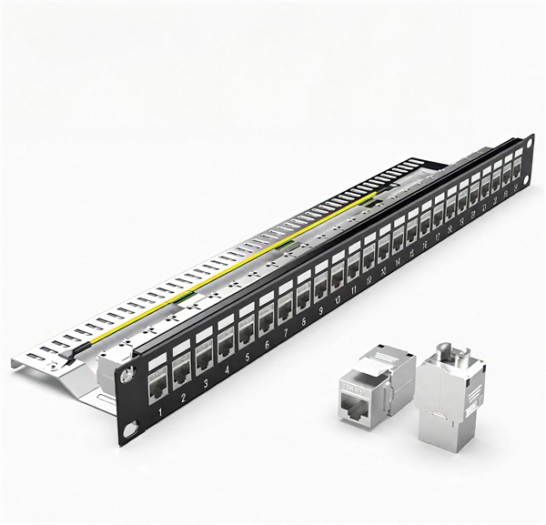
A typical fiber connector (the plug-and-socket type you'd find on patch panels) adds around 0. 5 dB of loss per connection. Higher-quality connectors under ideal conditions can get down to about 0. Attenuation in fiber optics is the gradual loss of light signal strength as it travels through a fiber cable. It's measured in decibels per kilometer (dB/km), and it determines how far a signal can travel before it becomes too weak to read. A standard single-mode fiber operating at 1550 nm loses. Optical Signal Attenuation is the single greatest factor limiting the distance and performance of your network. Understanding it is crucial for anyone involved in data centers, telecommunications, or enterprise networking. This guide will demystify signal loss, explore its causes, and show you how. F iber optic networks rely on the efficient transmission of light signals to deliver high-speed data over long distances. However, various factors can cause signal degradation, leading to performance issues and reduced network reliability. Fiber optic signal loss, also known as attenuation, occurs. Home1 / Blog2 / fiber optic3 / How to Fix High Attenuation & Signal Loss in Fiber Optic Networks. Signal loss in Fiber Optic networks can make data slow. High attenuation makes your system not work well. You may see slower speeds and less steady connections when signal loss goes up. Things like impurities in the fiber core and reflections at the core-cladding edge cause this drop.
[PDF]
Function: Analog switches are designed to pass or isolate analog signals. They essentially route analog signals based on a control signal. Examples: The CD4066B (CMOS Quad Bilateral Switch) and the SN74HC4066 (quadruple bilateral analog switch) from Texas Instruments are popular. Solid-state analog switches and multiplexers have become an essential component in the design of electronic systems which require the ability to control and select a specified transmission path for an analog signal. These switches provide bidirectional connections when “on” and high impedance paths when “off. Analog inputs are used to measure changes in process through sensors, subsequently converting that signal to voltage or current and sending it to modules that measure this change to determine new setpoints. Many remote and local I/O systems can use discrete and analog input signals. What. In the example below, an RF input signal is added to a DAC output or switched to GND. Due to the high frequency of the RF signal, any switching transients of the switch would disturb the RF output signal, thus any. Texas Instruments offers a wide variety of switches and multiplexers supporting a variety of configuration, voltage, bandwidth, and package needs. This application note summarizes the key features and performance characteristics of our analog signal switches and application considerations for.
[PDF]

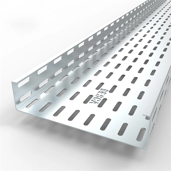
Cable trays are mechanical support systems that provide a rigid structural system for electrical cables, raceways, and insulated conductors used for electric power distribution, control, signal instrumentation, and communication. Cable trays are used as an alternative to open wiring or electrical conduit systems, and are commonly used for cable management in. maintain spacing or to keep cables in place when the tray is ect the minimum bend ra-dius for cables as they exit the bottom of the cable tray. Metal cable trays are made of galvanized steel, stainless steel, and. The modern world relies heavily on electrical and communication cables that must be managed and supported across vast distances in commercial and industrial settings. A cable tray is an organized support structure designed to secure and route these insulated electrical cables. It acts as a. For safe application, observe the following: WARNING To prevent from shock, short-circuits or damage, observe the following: • Be sure the power is disconnected before replacement (fuse exchange, etc. • Use this product in a properly maintained condition. (Replace or repair if the body. What is a cable tray? A cable tray is a metal or non-metal structure used to lay electrical cables and wires, serving to support, protect, and guide the cables. What is the role of a cable tray in electrical engineering? A cable tray allows for the neat and aesthetic arrangement of cables.
[PDF]
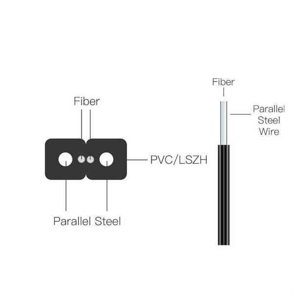
Modern fiber-optic communication systems generally include optical transmitters that convert electrical signals into optical signals, optical fiber cables to carry the signal, optical amplifiers, and optical receivers to convert the signal back into an electrical signal. The information transmitted is typically digital information generated by computers or telephone systems. Transmitters The most commo. OverviewFiber-optic communication is a form of for from one place to another by sending pulses of or through an. The light is a form of. First developed in the 1970s, fiber-optics have revolutionized the industry and have played a major role in the advent of the. Because of its advantages over electrical transmission, optical fiber. is used by telecommunications companies to transmit telephone signals, Internet communication and cable television signals. It is also used in other industries, including medical, defense, governmen.
[PDF]

