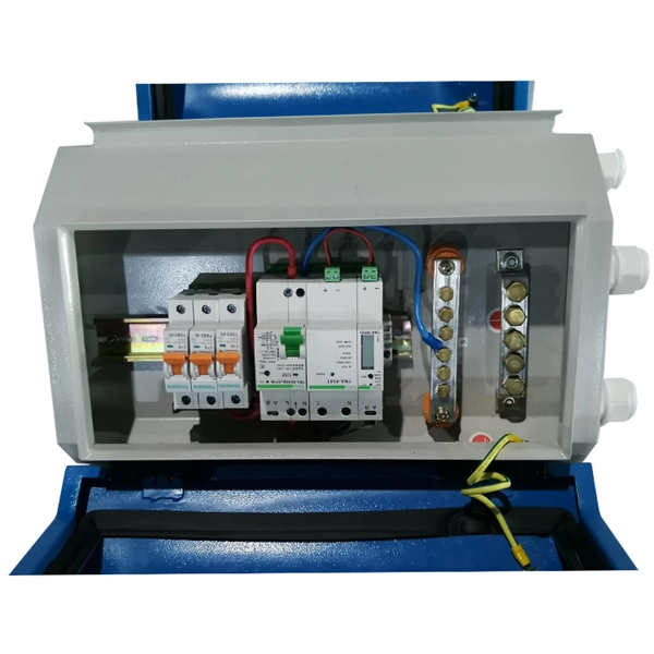
They provide cost-effective solutions through automated dispensing and streamlined production. With the durability, robust IP67-rated protection, and resistance to vibration and environmental factors, these boxes deliver reliable performance in harsh conditions. A distribution boxes is an essential device that manages the safe and efficient flow of electrical power throughout different areas of a building or facility. It is commonly used in homes, offices, and industrial settings to control and protect electrical circuits. Understanding its significance. Many people think distribution boards and distribution boxes are the same, but they're not. They may sound similar, but they have different roles in electrical systems. Knowing the difference helps you choose the right one for your needs. But how do you choose the right one for your application? In this article, we break down the key types, core functions, and selection tips to help you make an. A distribution box, also known as a power distribution box or electrical distribution box, is used to distribute electrical power safely to multiple circuits. It helps organize, protect, and control electrical connections in residential, commercial, and industrial electrical systems. What is the distribution box? A. One critical component of a septic system is the distribution box (also called a d box). The D box is a.
[PDF]

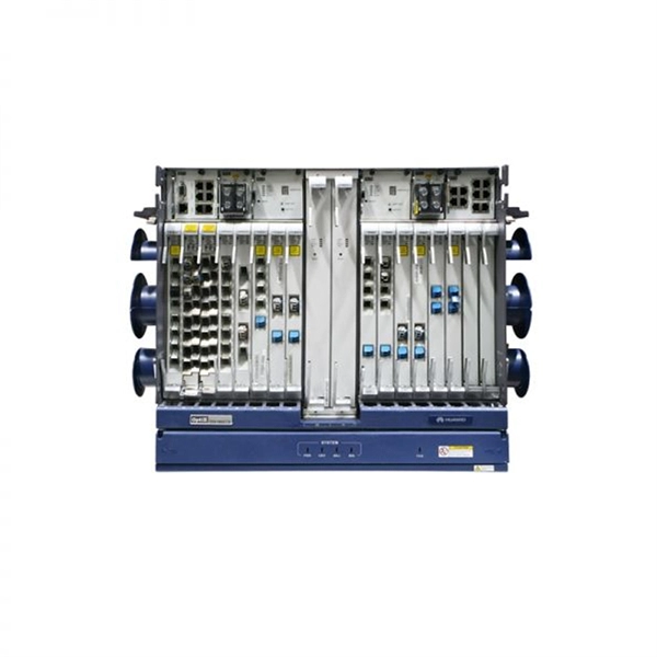
This report lists the top Fusion Splicer companies based on the 2023 & 2024 market share reports. Mordor Intelligence expert advisors conducted extensive research and identified these brands to be the leaders in the Fusion Splicer industry. Fujikura Europe Ltd offers fusion splicers, which are essential for efficiently joining optical fibers. As the official support center for Fitel splicers, OFS. AFL - Fiber optic cable, transmission and substation accessories, outside plant equipment, connectors, fusion splicers, test and inspection equipment. Discover how these fusion-spliced, field-installable connectors simplify installation and improve performance. Are you looking for a professional and reliable fiber optic products manufacturer for your business? Are you still worried about how to find and select a best partner from so many fiber optic products manufacturers? Don't be afraid, Gcabling will help you. In this post, Gcabling, as a professional. Fiber splicing is the process of joining optical fibers to create continuous, low-loss optical pathways used in manufacturing, research, and high-performance fiber systems. In advanced applications, fiber splicing is not a single operation. They are headquartered in locations across the globe, including the United States, China, Brazil, and India, with founding years ranging from 1964 to 2019.
[PDF]

Cable trays are mechanical support systems that provide a rigid structural system for electrical cables, raceways, and insulated conductors used for electric power distribution, control, signal instrumentation, and communication. Cable trays are used as an alternative to open wiring or electrical conduit systems, and are commonly used for cable management in. maintain spacing or to keep cables in place when the tray is ect the minimum bend ra-dius for cables as they exit the bottom of the cable tray. Metal cable trays are made of galvanized steel, stainless steel, and. The modern world relies heavily on electrical and communication cables that must be managed and supported across vast distances in commercial and industrial settings. A cable tray is an organized support structure designed to secure and route these insulated electrical cables. It acts as a. For safe application, observe the following: WARNING To prevent from shock, short-circuits or damage, observe the following: • Be sure the power is disconnected before replacement (fuse exchange, etc. • Use this product in a properly maintained condition. (Replace or repair if the body. What is a cable tray? A cable tray is a metal or non-metal structure used to lay electrical cables and wires, serving to support, protect, and guide the cables. What is the role of a cable tray in electrical engineering? A cable tray allows for the neat and aesthetic arrangement of cables.
[PDF]

Every fiber optic patch cable has a rated attenuation and bandwidth. For example, OM1 is rated at 200 MHz·km at 850 nm and is intended for use in legacy applications. The higher OM ratings provide more speed and distance. Attenuation should remain within acceptable limits for reliable transmission. Executive Summary: Choosing the right fiber patch cable is one of the most consequential decisions in network infrastructure planning. The wrong choice — whether it's an underperforming multimode grade or an unnecessarily expensive singlemode run — can either cripple your network's reliability or. Fiber optic patch cords are key components for efficient, low-loss optical signal transmission between devices and fiber optic cabling links. One or both ends of the patch cord are equipped with standardized fiber optic connectors, and common interfaces include LC, SC, FC, ST, etc. They are manufactured and tested in compliance with TIA 604 (FOCIS), IEC 61754 and YD/T industry standards. OM1, OM2, OM3, OM4, OM5 or OS2 fiber types are available to meet the demand of. Fiber optic patch cables are ideal for supporting high speed telecommunication network fiber applications. They are lengths of optical fiber terminated with connectors on both ends. Their job is to connect two optical devices, like switches, routers, or optical transceivers that communicate.
[PDF]

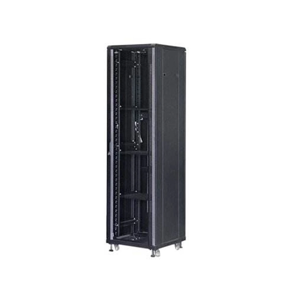
A distribution box, also known as a junction box or distribution point, is a enclosure or housing used to distribute electrical or telecommunications cables to multiple directions. A distribution box (DB box) is a key part of electrical wiring, acting as a central hub where cables branch out to various outlets and switches in a building. It supports different cable sizes and types, enabling smooth and fast power distribution. Each. Distribution boxes, also known as electrical distribution boards or panels, are pivotal components in electrical systems, ensuring the safe and organized distribution of electrical power throughout residential, commercial, and industrial environments. These boxes house various circuit breakers. With the new distribution box, centrally routed cables can be distributed 360° in all desired directions. Cables with and without connectors can be routed, sealed with IP54 (acc. to 60529) and strain relieved in accordance with EN 62444. This article will provide a detailed introduction to electrical distribution boxes, including their functions, components, types, and uses. Today, electrical systems are essential for homes and industries. But what exactly is a power distribution box, and why is it so essential in our daily lives? The DB panel board controls the flow of electricity.
[PDF]

The two primary industry-accepted methods for fiber optic cable splicing are fusion splicing and mechanical splicing. The choice between them depends on performance requirements, budget constraints, and the specific application environment. To begin, the standard definition of splicing in optical fiber is joining two fiber optic cables together. Splicing is most commonly used in the field but has application in cable assembly houses. Infield. In this guide, we cover the basics of fiber optic splicing, how to perform splicing using two different methods, and finally some best practices to perform good fiber splicing. What is Fiber Optic Splicing and Why is it Needed? – #1. In this guide, we'll explore what splicing of fiber entails, why it's important, and dive into the key methods and tools. So in essence, fiber optic splicing is a process used to join two separate fiber optic cables together. Through splicing, fiber optic technicians can extend the length of the fiber to make it long enough for use in a required cable run. As. Splicing fiber optic cable is an extremely important phase for making dependable, high-speed communication infrastructures. Termination is the other, more frequent way of linking fibers. Fiber splicing is the preferred way when cable lines are too long for a single length of fiber or when combining two different types of cable.
[PDF]

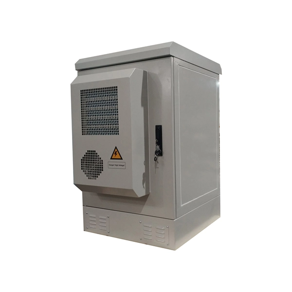
Key components typically housed within these boxes include circuit breakers, relays, fuses, and switches, all critical for safe electrical distribution in hazardous environments. Flameproof enclosure (Ex d IIB+H2), which can be used as feed distribution equipment in control and distribution system (such as distribution box, switch box of main circuit, control box, terminal box or motor starting box etc. ) ·Enclosure: stainless steel. Equipped with specialized hinge. Explosion proof equipment is designed to contain internal explosions and prevent ignition of surrounding flammable gases or dust. Rather than stopping an explosion from occurring, the equipment safely manages it within a reinforced structure. They house critical components like circuit breakers, relays, and surge protectors in durable materials such as aluminum or stainless steel. They ensure electrical safety by preventing sparks or heat from igniting flammable substances. As industries evolve, understanding how these devices operate becomes essential for engineers, safety managers, and. Explosion-proof Power Distribution Panel MAMX-02 and MAMX-03 * In-built circuit breaker, AC Contactor, Thermorelay, PLC, Transducer, Soft starter and other components, The panel can install indicator, Pushbutton, Universal switch, Display instrument. * Rated current: 1500A * Steel pipe or Cable.
[PDF]

Members of the Cabinet are political appointees and administratively operate their departments. For the current cabinet, see Second cabinet of Donald Trump. The Cabinet of the United States is the principal official advisory body to the president of the United States. The Cabinet generally meets with the president in the Cabinet Room adjacent to the Oval Office in the West Wing of the White. Every President has a lot to do -- especially a modern-day United States President. He or she must: oversee dealing with foreign countries and the defense of our land. keep an eye on how our farms are doing. make sure that. The purpose of the Cabinet is to advise the President on matters relating to the duties of their respective offices. The Constitution does not directly mention a "Cabinet," but. cabinet, in political systems, a body of advisers to a head of state who also serve as the heads of government departments. The cabinet has become an important element of government wherever legislative powers have been vested in a parliament, but its form differs markedly in various countries, the. The Presidential Cabinet acts as a set of advisors for the president. What Is the US Cabinet? The US Cabinet is a series of departments within the.
[PDF]
The voltage in Turkmenistan is 230 volts and the frequency is 50 Hz. Turkmenistan has standardized on type C and type F sockets and plugs. Type E plugs can also be used thanks to their compatibility with type F sockets. If your device plugs don't match Turkmenistan's standards, we recommend purchasing suitable travel adapters in advance to ensure proper use. What power plug types are used in Turkmenistan? Plug type B. Ok, you are going to Turkmenistan, you will use power plugs/outlets similar to the following picture (s): (includes Ashgabat, Mary, Turkmenabat, Dashogus, Konye-Urgench, Turkmenbashi. (more details after you choose where. Everything you need to know about Turkmenistan power outlets, plugs for Turkmenistan, power adapters, voltage, and frequency when travelling to Turkmenistan. Planning a trip to Turkmenistan and wondering if you need a power adapter? Look no further! We've got you covered with this comprehensive. Turkmenistan uses power outlets and plugs of types C & F. Take a look at the pictures below to see what these plugs and power sockets look like: Doesn't look familiar? Do the outlets look different in your country? You'll need a power plug adapter. 220 V has an advantage over lower voltage such as the 110 V that it is cheaper to transmit. On the other hand, 220 V is more dangerous than lower voltages.
[PDF]
Steel tape armored (STA) fiber optic cable is a reinforced cable structure designed for underground environments where mechanical protection is critical. This cable design is commonly installed inside underground ducts or conduits where fiber cables require protection from external pressure and environmental conditions. GYTS. nded water-blocking tape and corrugated, laminated steel tape. The cable features steel wire strength mem member with water swellable threads and water swellable tape. Helically applied wa erblocking e-glass non metallic strength members with ripcord. Corrugated Steel Tape (CST) armouring and. ape Armored Cables is a central tube cable using optical fibres presented in loose tube and surrounded by Steel Tape armor. To protect the optical fibres from water ingress, the tube is filled with a thix tropic gel, and is enclosed in a thermoplastic sheath. The cables have embedded strength. ESCAB GYTY133 - fiber cable is stranded loose tube structure with steel tape double sheaths, the loose tube stranding technology make the fibers have good secondary excess length and allow the fibers free movement in the tube, which keeps the fiber stress-free while the cable is subjected to. Corrugated steel tape armored fiber optic cables are engineered for durability and performance in demanding environments. These cables combine optical transmission efficiency with robust mechanical protection, making them ideal for outdoor, underground, and industrial installations.
[PDF]
By providing a physical air gap via photoelectric isolation, this 817 optocoupler board ensures that noise or electrical faults on the load side never reach your expensive processing unit. This voltage level shifter is designed for high-reliability interface driving. Onboard 4-Channel 817 Are Independent:can achieve different voltage control at then same time The output ports are independent of each other. Module Diagram: One Channel of the 4-Channel Optocoupler High-Power Motor Drive Module. Optocoupler Isolation Relay Mo. AC 110V Motor Forward Reverse. The FOD3182 is a 3A output current, high-speed MOSFET gate drive optocoupler. It consists of an aluminium gallium arsenide (AlGaAs) light emitting diode (LED) optically coupled to a CMOS detector with PMOS and NMOS output power transistors integrated circuit power stage. It is ideally suited for. An optocoupler, also known as photo-coupler or opto-isolator, is a component which can transfer an electrical signal across two galvanically¬-isolated circuits by means of optical coupling. Inside the package, an infrared LED on the input side shines onto a phototransistor on the output side. They are sometimes known as opto-isolators, photocouplers, or optical isolators.
[PDF]
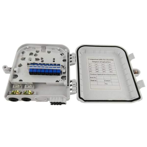
The fiber optic terminal box is the terminal connector of the fiber optic cable, one end is the fiber optic cable, and the other is the tail of the fiber optic cable. This is equivalent to a user's cable terminal box. Pigtail: Used inside termination boxes to connect the optical fibers in the fiber optic cable to pigtails or other components. Fiber patch cord: A fiber patch cord has connectors on both ends and is used to connect. Where copper twisted pairs tend to terminate with an RJ45 plug, fiber optic connectors come in all sorts of shapes and sizes, with all manner of different use cases in mind. An optical fiber connector is used to join optical fibers where a connect/disconnect capability is required. The fiber. The terminal box is a fiber management product used to distribute and protect optical fiber links in FTTH networks. By understanding the components, types, and differences between various fiber management devices, businesses can make informed decisions when deploying and maintaining their fiber. The fiber termination box is an interface between the fiber cable from the line side and the pigtails to be passed to the fiber distribution frame. Key Functions Typical Applications ZION FTB Highlights In essence: The Fiber Terminal Box is an end-user termination device for small-scale distribution. ■ What Is a Fiber.
[PDF]

While the concept is the same, pigtails generally fall into two distinct categories based on the medium they transmit: electrical current or light signals. These are found in cars, appliances, and home wiring. They carry voltage and ground. A pigtail connector is a short cable with a connector on one end and bare (stripped) wire or fiber on the other. In fiber optics, pigtails are fusion-spliced to field fiber inside splice trays — the most common termination method in telecom and data center networks. In electrical work, pigtails. Whether it's an electrical system in your car, home, or factory, the quality of the connection is essential, and that's where pigtail connectors come in. These small, often overlooked components ensure a strong, safe electrical connection. It allows easy integration of connectors into systems where direct termination is difficult. Pigtails are widely used in RF, fiber. What Is a Pigtail in Electrical Wiring? If you've ever tackled an electrical wiring project, you've likely heard the term "pigtail" thrown around. It might sound like something out of a farmyard, but in the world of wiring, it's a simple yet essential technique. It serves as a bridge, allowing technicians to repair specific connection points without disturbing the rest of the system. As technology continues to advance, a variety of optical pigtail types have emerged, each designed to meet specific requirements and.
[PDF]