Creating a 90-degree elbow in an electrical cable tray, often called a "fabricated" or "mitered" bend, involves cutting, bending, and fastening a straight section of tray. The most common method involves creating two 45-degree cuts to form a 90-degree angle. Use this tool to estimate sloped section length, horizontal run requirement, cut marks, and installation feasibility. Measure this distance along the straight tray. Depends on the type of cable tray, you can buy 90° tray fittings or use a speed square with a straight edge and a grinder or skill saw to cut 45° cuts. Do you want a hard 90 or 2 spaced out 45° bends? Need dimension of tray first width x side wall. Also need to know if you're bending inside or. Key Concept/Formula: To create a 90-degree turn in a cable tray, a mitered joint is used, which involves cutting two pieces of cable tray at a 45-degree angle each. Key Concept/Formula: For a precise 45-degree cut, if the width of the. By applying the following formula you can quickly find the size of cut out section that you need to cut out of the side of the cable tray, or gutter-type section to make that angle. First, you have to find (C) which is found by dividing 90° by (B) 22° = 4. You can then calculate the size.
[PDF]
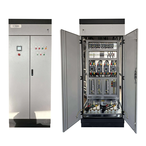
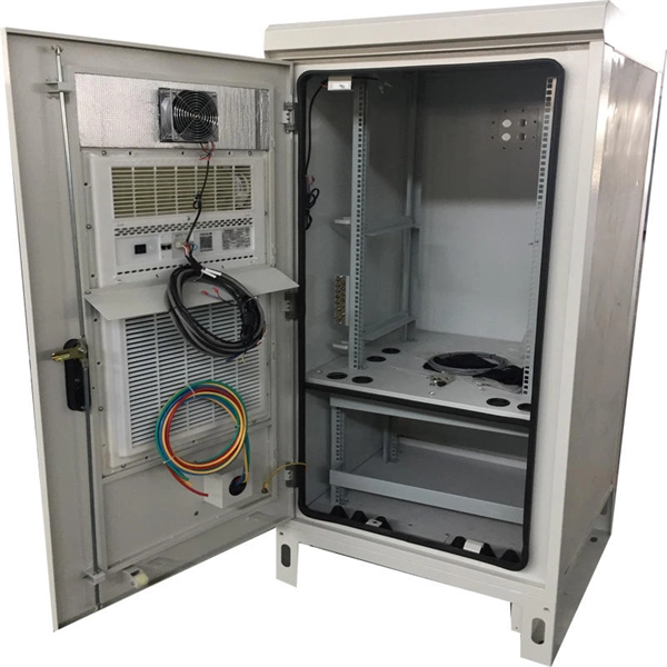
In this video, we'll walk you through the process of wiring a home distribution box with a detailed connection diagram. Whether you're an electrician or a DIY enthusiast, this guide will help you understand the basics of home electrical distribution. more Welcome to our channel! In this video. An electrical panel box, also known as a breaker box or a distribution board, is a crucial component of any electrical system. It serves as a central hub for distributing electricity throughout a building, ensuring that power is delivered safely and efficiently to all the required locations. Distribution Board or DB is an electricity supply system or a common enclosure that distributes the electrical power feed into subcircuits. It includes isolator, RCCB (Residual current circuit breaker) or RCD (Residual-current device) devices, protective fuses or MCB's (Miniature Circuit Breaker). Learn how to install a distribution box safely and correctly. Covers wiring, placement, standards, and expert tips for a compliant setup. It takes the incoming power and safely distributes it to different circuits throughout your building. Box installation: Make sure that Distribution box has been correctly installed and fixed. Material preparation: Prepare the required circuit breakers, wires, wiring ties and other materials, and ensure that they meet the design drawings and installation requirements. To understand how a breaker box works, it is helpful to.
[PDF]

We are a top Cable tray Suppliers and Wholesalers in Nepal, Supplying Cable tray at Factory Prices. Call +919310048509. If you are looking for Wire Mesh Cable Tray Manufacturers in Nepal, although we are located in Delhi, we fabricate trays using mild steel and GI, enhanced with Hot-Dip Galvanized or stainless-steel finishes. Our production methods ensure that the trays can hold a lot of weight while being lighter. Jeetmull Jaichandlall (P) Ltd. We believe in building fruitful business partnerships. Every buyer chooses us first because of our excellent finishing and high-quality. We manufacture many types of cable trays and their accessories in Nepal. We use high quality raw materials and most advanced technologies guaranteeing total fulfillment at customers end. Thickness - 3mm, 4mm, 5mm, 6mm. Height - 25mm,40mm, 75mm and 100mm. 75in PVC Desk Cable Tray Under Desk Cable Management Channel Cord Hider No Drilling Installation Wire Organizer Nepal - Shop for Best Online at Daraz. np Wide Variety of pvc cable tray. Great Prices, Even Better Service. Call +919310048509.
[PDF]

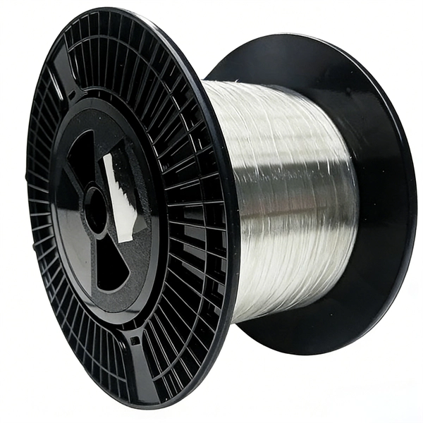
The OMERIN Group is the world's leading manufacturer of cables for extreme conditions (-190°C to +1400°C). Find here High Temperature Cables, High Temperature Wires manufacturers, suppliers & exporters in India. Ideally for a wire to be classified into this category needs to have a temperature rating of 125 degrees C. The High-Temperature Wires can either be a multiconductor or a single conductor. To find out. Established in 1990, Thermo Cables Limited has evolved into a leading manufacturer of specialty cables, serving diverse industries such as Railways, Navy, Defence, Renewable Energy, Nuclear Power, Process Industries, Oil & Gas, and Power sectors. As part of Thermo Group, we are seamlessly. 'Udeytemp' is a specially developed asbestos free insulation material for high temperature use can be insulated on all types of cables covering a vast variety of applications. and. Jiangsu and Zhejiang provinces specialize in industrial-grade cables, hosting facilities like Jiangsu Plaza Premium Electric Instrument and Zhejiang Teflon Wire & Cable with 5,400–6,200 m² production areas. Guangdong's Shenzhen and Dongguan regions focus on high-volume exports, evidenced by. The list above is filled with wholesale jumper wire suppliers, wholesalers, factories, manufacturers (OEM, ODM & OBM), importers, exporters, agents, and more that are certified and verified by Global Sources.
[PDF]
Pictures and step-by-step instruction for splicing household electrical wiring to extend a circuit. Connecting wires to your home distribution box? See how electricians do it professionally! From selecting the right wire gauge to safely connecting the main. A distribution board or distribution box is where the main power supply is distributed to multiple loads. And all the switching and protective devices are installed in the distribution box. Single Phase Distribution Box generally consists of Double Pole MCBs, Single Pole MCBs, and RCCBs. Covers wiring, placement, standards, and expert tips for a compliant setup. It takes the incoming power and safely distributes it to different circuits throughout your building. Whether you're an electrician or a DIY enthusiast, this guide will help you understand the basics of home electrical distribution. What is Distribution Board? Distribution board. Always begin with disconnecting the main supply before accessing any enclosure containing distribution components. This prevents arc faults and ensures safety when modifying or inspecting current paths. Inside the service housing, line conductors from the utility feed typically enter through the. A plastic connector, called a wire nut, is used to insulate and secure the splice. Wire splice connections must be housed inside a covered electrical box, known as a junction box. A junction box is usually square.
[PDF]

Have all of our in-stock product information and specifications right at your fingertips in digital PDF format. is a world class manufacturer of electronic wire and cable, both copper and fiber optic cable. Because of NATIONAL's service attributes and extensive cable manufacturing abilities, we offer a unique set of brand attributes: personalized service and product selection. You can get just about any. DOWNLOAD the Complete Catalog (PDF format 3. 9 MB) Download part numbers, descriptions and specifications of National Wire in-stock products by specific category or download the entire catalog. Heavy-Duty Flexible PVC Insulation – Crack-resistant and built for long-term durability. Versatile Use – Perfect for automotive, solar wiring, LED lighting, home projects, and RV systems. Guaranteed for. Fill out the form with your project details, and we'll help you every step of the way. Feedback! Don't miss out on anything, subscribe to our Newsletter! NNC © Copyright 2009 - 2026. Forgot your password?. Important! LANshack offers premium fiber optic cable & copper wire assemblies. We have all the components to optimize & install your network!. welcome to taobao purchase national standard soft copper wire 25 square millimeters 16 square millimeters copper core cable high-volume building welding machine welding wire welding machine welding machine welding soft copper wire.
[PDF]

The easiest way is to use the $3 "spec-grade" receptacles which come in a box instead of loose in a bin. If it's just black and white wires with a cloth or plastic covering and no ground wire you'd need a retroit grounding wire to have grounded outlets. A clearer picture of the cable entering will help. Can you post photos that show clearly where the cables enter the box at, please? @Traveler No!. The process of wiring a small breaker box, often called a subpanel, is a common task when adding power to a detached structure like a shed, garage, or a major home addition. These smaller distribution centers are designed to take power from a larger main service panel and distribute it locally to. How do I wire a mini circuit breaker distribution box that doesn't have bus bars? I have a circuit going to my shed from my house and I want to have two separate breakers inside the shed (one for outlets, one for other stuff) so I bought this from amazon (Amazon. com: 2 Way Distribution Box Circuit. In this video, we'll walk you through the process of wiring a home distribution box with a detailed connection diagram. more Welcome to our channel! In this video. Connecting a distribution box involves several steps to ensure proper electrical flow. But first, the rules: Turn off the power when working with electricity. Make sure the power's off using a non-contact voltage tester or multimeter. One final tip: Get into the habit of making connections in this.
[PDF]

Calculate horizontal, vertical, or compound cable tray offsets based on bend angle, offset distance, and available installation space. Use this tool to estimate sloped section length, horizontal run requirement, cut marks, and installation feasibility. Click "Calculate" to see the minimum bending radius and the recommended standard tray bend radius (300mm to 900mm) required for safe installation. Tray bend radius must be ≥ minimum cable bend radius. Use the largest cable diameter in the tray for calculation. Always select the next higher standard. Would someone kindly let me know the formula to create a flat 45 in say 100 mm cable tray for example. So I can then use the formula on different cable tray sizes and to different angles. the cable tray is 3 metres in length, this doesnt matter but i think the width does. each bend is a 45 degree angle. but the length of the part in the centre is the concern as i have seen different. The method for producing bridge bend elbows is as follows: Take a 90-degree cable tray bend elbow as an example, and apply the same principles for 45-degree bends accordingly. The length of the bottom side (bottom diagonal) after bending the cable tray should be equal to the width of the cable. How to bend 22. 5 degree of cable tray 3 layer with the same distance and gap • HOW TO BEND 22. 5 DEGREE OF CABLE TRAY 3 LA. Measure this distance along the straight tray.
[PDF]

It is home to a full range of terrain and over 200 routes for climbers of all abilities. 25+ new routes are set every Friday. Additionally, the gym features a full training area with a Tension Board + MoonBoard + Kilter Board, a dedicated kids area, yoga rooms, huge garage doors, and. A classic Bend bouldering spot is upstream of the Bill Healy Bridge on the west side of the Deschutes River Trail. Walk over the bridge, to the left, and upstream for about 15 minutes. There are five officially recognized problems in the area, known locally as “The Depot,” ranging from grades. Climbing Area Map This is our best guess at this area's location. This area is for the bouldering roughly concentrated around the town of Bend. A walk along the Tumalo Creek trail will reveal hundreds of possible boulder problems that have yet to be brushed off and recorded. Walking through. A climbing destination in 2026 can typically only offer two of three critical assets: Duration, Accessibility, and Connectivity. You must choose your compromise. Central Oregon offers a variety of climbing, from bouldering to sport and trad climbing. If you're. Our walls have lots of options for first time climbers, and we have a beginner circuit of climbs for you to work towards mastering. Not at all! While we do require all climbers to use climbing shoes, we have rental shoes and chalk available to rent for $5. Board climbing seems intimidating, is this.
[PDF]
The zinc plating on these tray systems offers good corrosion resistance. Cut, bend, and connect the wire mesh trays to route cable and hose in configurations such as curves, slopes, and tees. They are a ligh.
[PDF]
This guide provides a detailed, professional procedure for installing a Residual Current Circuit Breaker (RCCB)—a device essential for protecting people from the severe danger of electric shock. The steps outlined here are fundamental to ensuring the RCCB functions. It is an electrical protective device that protects electrical circuits and devices from some electrical faults such as leakage faults, electrical shock, current unbalance due to equipment failure, etc. It works on the principle of sensing residual current which is why it is called a residual. Distribution board is a safe system designed for house or building that included protective devices, isolator switches, circuit breaker and fuses to connect safely the cables and wires to the sub circuits and final sub circuits including their associated Live (Phase) Neutral and Earth conductors. Residual-current devices, commonly referred to as RCDs, are used in many practical applications. They can be found in fuse boxes, electrical switchgears or industrial machine control systems. Therefore. To wire an RCD fuse box correctly, start by reviewing the diagram to identify each circuit and its corresponding components. Understanding the layout helps prevent mistakes and ensures safe wiring. floor in a multi storey building. The Sub distribution board is connected and supplied from the Main Distribution Board through different wires and cables rated.
[PDF]
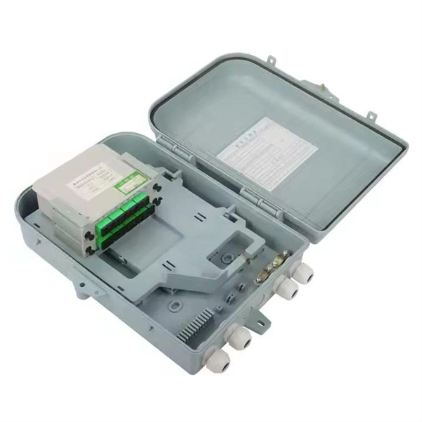
This video shows real on-site footage of electrical installation, demonstrating safe and standardized wiring methods used by professionals. more Learn how to wire a distribution box step by step! This video shows real on-site footage of. Material preparation: Prepare the required circuit breakers, wires, wiring ties and other materials, and ensure that they meet the design drawings and installation requirements. Location determination: Determine the installation position of the circuit breaker according to the position of the. Learn how to install a distribution box safely and correctly. Covers wiring, placement, standards, and expert tips for a compliant setup. A distribution box is the heart of any electrical system. It takes the incoming power and safely distributes it to different circuits throughout your building. It serves as a central hub for distributing electricity throughout a building, ensuring that power is delivered safely and efficiently to all the required locations. This video highlights the installation process for CANTEX Exposed Weatherproof PVC electrical boxes. When an electrical connection is needed outside of a home, commercial or industrial building---or anywhere it might be exposed to the elements, weatherproof electrical boxes and covers are required. It has three categories: residential, commercial and industrial electrical distribution boxes, all of which play important roles in their respective electrical.
[PDF]
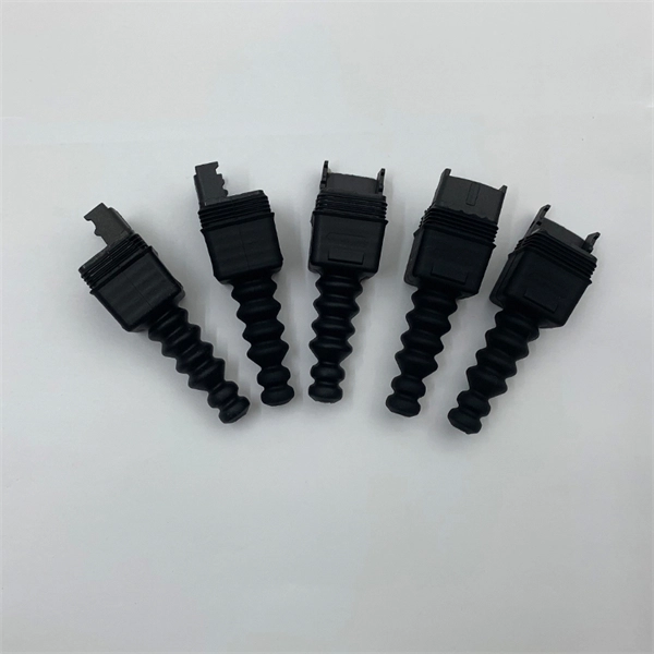
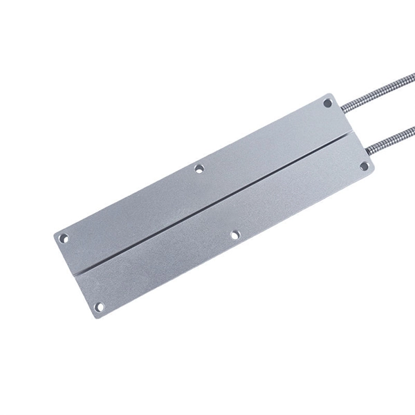
This guide summarizes field-proven rules for AI/AO/DI/DO wiring, shows how to choose between NO/NC contacts under the fail-safe principle, and explains how to decode typical cable schedule entries. Instrument installation with the associated cable installation/electrical signal and control wiring should be carried out by skilled personnel who are acquainted with the safety requirements and regulations for the plant site for that specific project. Generally instrument cabling is usually run in. Few factors are to be considered or taken care of while wiring a field instrument to control panel. Based on noise susceptibility limits (NSL) according to IEEE 815 standard, various field instrument signals are classified as below. Noise Susceptibility Limit Grounding of the signal cable Type of cable Cable Terminations Based on noise susceptibility limits (NSL). Note how the hoop-shaped “jumper” wires are all cut to (nearly) the same length, and how each of the wire labels is oriented such that the printing is easy to read: This next photograph shows a great way to terminate multi-conductor signal cable to terminal blocks. Each of the pairs was twisted. A well-designed and properly installed instrument junction box is crucial for the efficient operation and maintenance of electrical systems. Level 1: High to medium susceptibility Level 2: Low susceptibility.
[PDF]