For example, in a FTTH network, a single fiber from the telecom provider can serve 32 homes using a 1:32 splitter, eliminating the need for separate fibers to each residence. These unassuming devices enable a single optical signal to be divided into multiple paths, making them indispensable for sharing network resources efficiently—from residential FTTH (Fiber-to-the-Home) connections to large-scale telecom backbones. This guide demystifies fiber optic splitters. You use optical couplers and splitters to split or join signals in fiber networks. These devices help you control light signals well. For example, optical splitters send light to many output ports. It can divide the input optical signal into multiple output optical signals to meet the fiber optic access needs of multiple terminal devices. This type of device plays an important role in passive. A fiber-optic splitter, also known as a beam splitter, is based on a quartz substrate of an integrated waveguide optical power distribution device, similar to a coaxial cable transmission system. The optical network system uses an optical signal coupled to the branch distribution. The fiber optic. If you've ever wondered how a single fiber from your internet service provider can deliver service to an entire neighborhood or apartment building, you've wondered about the magic of optical splitters. The process of light beam splitting involves.
[PDF]

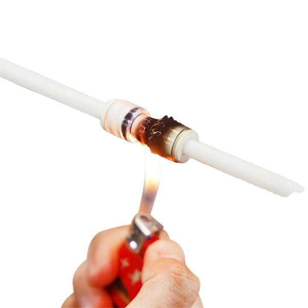
Huawei's fiber to the room (FTTR) solution extends fibers to rooms and provides various gigabit Wi-Fi 6 master/slave FTTR units, all-optical components, and optical cable routing tools. This enables home users to enjoy stable gigabit Wi-Fi experience from anywhere in the home. FTTR is generally an extended FTTH (Fiber To The Home) solution. Drop optical cable terminates at ATB (Access Terminal Box). A patch cord of 1 or 2 m. Huawei will soon be selling its "FTTR" system for do-it-yourself fiber optic home cabling in Germany. Huawei FTTR: Bonding tool for fiber optic installation. A special glue. Fibeye provides FTTR(Fiber to the room) solutions, We specialize in Huawei-adapted FTTR solutions that can help you tap into new markets and grow your business. What is FTTR FTTR(Fiber-to-the-room), is an innovative solution that allows telecom operators to bring optical fibers directly into. Guess what, I spotted Huawei's transparent fibre optic offering! The best Wi-Fi is wired Last year, I wrote about Singtel's FibreEverywhere offering, which allows homeowners to install high-speed wired cabling in every room - without any drilling or trunking. Poor Wi-Fi coverage at home is a common. Watch the video to discover how to use the Huawei FTTR fiber installation kit to route transparent optical cables.
[PDF]
Scattering accounts for the greatest amount of attenuation in a fiber cable, between 95 and 97 percent. Light traveling through the fiber interacts with the densities as shown in the light and is then partially scattered in all directions. Fiber optic cables have many advantages, but one of the downsides just like with copper cable, is that it can experience what is called attenuation. Attenuation refers to the loss of light as it travels down the fiber. This can be due to a variety of factors: scattering and absorption, intrinsic. This attenuation is inevitable, so the smaller the attenuation value, the longer the transmission distance of the same optical power. The better the quality of this fiber patch cable. It indicates the amount of signal reflected back. At TREND Networks, we are frequently asked how much loss is allowed when conducting testing on fiber optic cabling. Unfortunately, it is not a simple answer and depends on several factors. So how do you determine acceptable loss? When testing fiber optic cabling, determining acceptable loss is. Understanding fiber loss is vital in maintaining a reliable, efficient network. Understanding it is crucial for anyone involved in data centers, telecommunications, or enterprise networking. Here are the details and instructions about each field and how they contribute to the calculation: 1. Attenuation Coefficient (dB/km): This value represents the inherent signal loss per kilometer of.
[PDF]
Z: Income under a nonqualified deferred compensation plan that fails to satisfy section 409A. This amount is subject to an additional 20% tax (TurboTax does not support this calculation). According to Newsweek, a record high percentage of Republicans from across the country now identify as part of President Donald Trump's Make America Great Again movement, with about two thirds defining themselves this way. Recent polling suggests that things may be a little different among Ohio. The upper-case (capital) letters in box 12 report different things to the IRS. Here's a list of what each one means. DD: Cost of employer-sponsored health coverage. This amount is subject to an. The numbers 45-47 on Trump's hat stand for him being elected as the 45th and 47th president of the United States. As you may recall, Trump lost the 2020 election, and as a result, he encouraged a mob of his followers to descend on the Capitol building on Jan. 6, 2021, as the election results. The abbreviation is all over the internet, usually accompanying long paragraphs of text. It's a form of abbreviation in which every letter is pronounced on its own, like DVD or VIP. (For more grammar fun, learn about the difference between acronyms and. What did Jesus mean when He said, “Take up your cross and follow Me”? In Matthew 16:24, Jesus told His disciples, “Whoever wants to be my disciple must deny themselves and take up their cross and follow me. Many people interpret the “cross” to.
[PDF]

The document discusses optical detectors used in fiber optic communications systems. It describes the functioning of PIN photodetectors and avalanche photodetectors (APDs). Their performance. An optital detector is a device that converts light signals into electrical signals, which can then be amplified and processed. Such detectors are one of the most important components of an optical fiber communcation system and dictate the performance of a fiber optic communication link. PIN Photodiode A PIN photodiode is a widely. Detectors perform the opposite function of light emitters. The most common detector is the semiconductor photodiode, which produces current in response to. It explains how these devices use optical fibers to measure quantities like temperature, mechanical strain, pressure, and vibrations by detecting changes in light propagating through the fiber. A central focus is on sensors based on fiber Bragg gratings, where the Bragg wavelength is sensitive to. Optical Power Meters: These devices measure the power of optical signals in fiber optic cables. This information helps in maintaining signal integrity and quality across the.
[PDF]

Optical Transmitter: Converts electrical signals into optical signals for transmission. Optical modules are devices used to connect network devices, transmit and receive data between network devices, and can be used to convert optical and electrical signals. The optical module is a very important component in an optical communication system. This article will introduce you to the. d launches the optical signals into an optical fiber. A fiber optic transmitter consists of an interface c rcuit, a source drive to make it compatible with the source drive circuit. The source drive circuit intensity modulates the opt cal source by varying the current through the source. But what exactly is happening inside this powerful little component?In this article, we'll pull back the curtain and explore the inner. Optical transmitters are a crucial component in modern telecommunications, enabling the transmission of data as light signals through optical fibers. In this comprehensive guide, we will explore the definition, importance, and evolution of optical transmitters, as well as their types, applications. Role: Convert optical signals back into electrical signals and reconstruct the transmitted information., PIN diode or avalanche photodiode). Demodulation circuitry to extract the transmitted data. These requirements define digital transceivers as well as analog receivers and transmitters.
[PDF]

In this guide, we'll walk you through the entire process of preparing fiber optic cable for splicing and termination to fiber connectors. We'll explore the necessary tools, safety precautions, and step-by-step procedures for cable connectors, mechanical and fusion. At the heart of any robust fiber optic network lies a crucial process: Preparing a fiber cable for termination of a connector or splice. Two types of splices are used in fiber optic cabling one is Mechanical the other is Fusion. Whether you're installing a new network, expanding an existing one, or. Splicing fiber optic cable is an extremely important phase for making dependable, high-speed communication infrastructures. Regardless of the type of fiber network you're deploying, be it for telecom, enterprise data centers, or smart city infrastructure, fusion splicing provides the benefits of. Think of a fiber optic cable splice as the seamless stitching that keeps data flowing through the delicate threads of a network—like a master tailor joining fabric with precision. This article explains when. We terminate fiber optic cable two ways - with connectors that can mate two fibers to create a temporary joint and/or connect the fiber to a piece of network gear or with splices which create a permanent joint between the two fibers. These terminations must be of the right style, installed in a. So in essence, fiber optic splicing is a process used to join two separate fiber optic cables together.
[PDF]
These electrical signals need to be converted into optical signals before being sent over long distances. This conversion is done using a device called a transceiver. These light pulses are then sent through the fiber. Fiber-optic communication is a form of optical communication for transmitting information from one place to another by sending pulses of infrared or visible light through an optical fiber. The light is a form of carrier wave that is modulated to carry information. Fiber is preferred. A small form-factor pluggable, or SFP optic module, helps connect network devices fast. It also changes optical signals back into electrical signals. This lets you send data far away. SFP modules work in many network. Optical fiber is the carrier for optical signal transmission.
[PDF]

How to Install a Fibre Connector into a Patch Panel (Easy fibre optic connector installation) How to Install a Fibre Connector into a Fibre Optic Patch Panel. How do you install fibre optic connectors?. Connecting a fiber patch panel to a switch is a critical step in setting up a fiber optic network. There are different types of connectors. In today's high-performance networks, fiber optic patch cables are the lifelines that ensure smooth data flow across switches, servers, and routers. Even the most advanced optical transceivers can only perform at their peak when paired with properly installed, clean, and precisely managed fiber. Choose an SFP module based on the fiber optic cabling that will be connected to the network switches. SFP transceiver modules almost always require two fiber optic cable strands. A Fiber Patch cord connects two devices. You plug it into a switch, router, or patch panel. It's ready to use out of the box. A pigtail is for splicing. You fuse it to a. With a railroad switch (patch panel), the train (data) can travel from A to B, C and even more destinations, otherwise it can only go from A to B, or C to D. This article, What Is a Patch Panel Used for?, has explained it thoroughly.
[PDF]

They are compliant with the QSFP+ MSA and IEEE 802. The optical transmitter portion of the transceiver incorporates a 4-channel VCSEL (Vertical Cavity Surface Emitting Laser) array, a 4-channel input buffer and laser driver, diagnostic monitors, control and. They are compliant with the QSFP+ MSA and IEEE 802. The 40G QFSP+ transceivers feature varying specifications to meet your unique network needs. This includes short. FS 40G QSFP+ optical transceiver module solutions offer a full range of QSFP+ modules from 150m to 80km reach, and used for high-density switching, routing and data center applications. Engineered for reliability and scalability, these transceivers ensure efficient and seamless communication across various network infrastructures. The QSFP+ module is designed for use in 40GBASE Ethernet throughput up to 10km, 30km or 40km over single mode fiber (SMF) using a wavelength of 1310nm via duplex LC connectors. Digital diagnostics functions are also available. QSFP+ Transceiver adopts 12 Fibers MTP/MPO Male connectors, reaching a link up to 150m over OM4 MMF (100m over OM3). 3ba 40GBASE-SR4 and breakout to 4x10GBASE-SR standard.
[PDF]
The features of a fiber termination box can significantly influence its price. Here are some key features to consider: 1. Splice Capacity:Higher capacity boxes will generally be more expensive, as they can accom.
[PDF]
The Fiber Optic Sensors market was valued at USD 2,560. 00 million in 2018, reached USD 3,547. Starting at USD 2. By 2035, it is projected to reach USD 6. 3% throughout the forecast period from 2026 to 2035. I need the full data tables. As per Market Research Future analysis, the Fiber Optic Sensor Market Size was estimated at 3. 08 USD Billion by 2035, exhibiting a compound annual growth rate (CAGR) of 10. 22% during the. Fiber optic communication relies on light waves, which are difficult to intercept or tamper with, making fiber optic sensors an attractive option for industries that require secure data transmission. I need the full data tables, segment breakdown, and competitive landscape for detailed regional analysis and. Global Fiber Optic Sensors Market Research Report By Type (Intrinsic, Extrinsic), By Component (Receiver, Transmitter, Fiber Optic Cable, Optical Amplifier), By End-User (Transportation, Medical, Defense, Industrial, Oil and Gas), By Region (North America, Europe, Asia Pacific, Latin America. Global Fiber-Optic Sensors Market Size By Type of Fiber-Optic Sensors (Intrinsic Fiber-Optic Sensors, Extrinsic Fiber-Optic Sensors), By Sensing Parameter (Temperature Sensors, Pressure Sensors), By Application Sector (Aerospace and Defence, Oil & Gas), By Technology (Fibre Bragg Grating.
[PDF]

Traditional turbidity monitoring methods involve the manual collection of water samples at set locations and times followed by laboratory analysis, which are labor intensive and time consuming. Fiber-optic measurement permits real-time, in situ turbidity monitoring. But the current technology is. This paper presents the development of an optical fiber sensor system for multiparametric assessment of temperature and turbidity in liquid samples. The sensors are based on the combination between fiber Bragg gratings (FBGs), intensity variation and surface plasmon resonance (SPR) sensors. Electrical, Electronic and Communication Engineering Dept. ; bFiber Photonics Department, UMR CNRS/University of Limoges 7252, 123 Avenue Albert Thomas, 87060 Limoges cedex, France; c“Grupo de Ingeniería fotónica”, Avenida Los Castr s. Turbidity is caused by the presence of suspended particles, organic matter, and chemicals, and is widely measured in natural resources, irrigation water, the food and beverage industry, and drinking water [1,2,3]. As an important water quality parameter, turbidity not only indicates the efficiency. Create a new folder below. Sensors were designed in two versions: for examination of liquid samples and for monitoring of transparency in the flow of liquids ('on-line'.
[PDF]

