Recommendation ITU-T L. 101 describes characteristics, construction and test methods of optical fibre cables for buried application. 0, in February 2016. First, in order to demonstrate sufficient performance of an. ion) and “ Installed” (after installation). The following formulas may be used to determine general guidelines for installing Corning Optical Communications fiber optic cable; however, refer to the cable specifi simply double the minimum working bend radius. Split cable guides and split 40-in. 1. The methods described are intended for guideline use only, as it is impossible to cover all the various conditions that may arise during an installation. Individual. The Fiber Optic Association, Inc. (FOA) was founded in 1995 to help develop the workforce to build the fiber optic networks to support a rapid expansion in communications and the Internet. The charter of the FOA was to promote professionalism in fiber optics through education, certification, and. Home / Instruction Sheets / Fiber Optic Cable Direct Burial Guidelines Need Help?. When planning a fiber optic network installation, one of the most common questions is: How deep are fiber optic cables buried? Proper burial depth is critical for the safety, durability, and performance of your communication infrastructure.
[PDF]

The machine is a hand-held free-to-height cable quick-attachment tool with internal components such as controllers that automatically complete all steps of cable tying. It can be widely used in the high-altitude operation in the field of communication engineering and is. Power Source: Rechargeable lithium battery Bundling range: 0-60mm Binding : can binding 1600 times for one time fully charger. Voltage: 12V Battery: 7800 mAh/group, Fully charged, one battery can work more than 1600 times, about 3 kilometers or more Battery installation mode: external and embedded. Delivery time is estimated using our proprietary method which is based on the buyer's proximity to the item location, the shipping service selected, the seller's shipping history, and other factors. Delivery times may vary, especially during peak periods. Buyer pays for return. Buy Newly Designed Second Generation High Altitude Optical Fiber Cable Bundling Machine for Efficient Network Installation at Aliexpress for. Find more 1420, 153713 and 1537 products. Enjoy ✓Free Shipping Worldwide! ✓Limited Time Sale ✓Easy Return. Maximum order quantity: 1 piece Customized logo (+ from /Min.
[PDF]

The optical power meter is similar to the voltohmmeter in application but measures the optical resistance (losses measured in dBm or dBM) of a cable before and after installation and provides a comparative analysis of the splices. The range of the meter is adjustable. Regularly testing fiber optic cables helps minimize network downtime, lengthens the network's longevity, reduces maintenance requirements, and helps support network reconfiguration and upgrades. These factors significantly add to the fiber optic network's long-term performance, manageability, and. Several types of tests are commonly conducted to assess and maintain the health of fiber optic networks. Continuity testing verifies that the fiber is intact and that light can pass through from one end to the other without any blockages. These test procedures assess the physical and functional qualities of fiber optic cables, connectors, and the network as a whole. Key tests include: Effective fiber testing utilizes advanced tools such as Optical. One way to test a splice is to use an Optical Power Meter. As the components like fiber, connectors, splices, LED or laser sources, detectors and receivers are being developed, testing confirms their performance specifications and helps. Regular testing of fiber optic cables is not just a preventive measure; it's an investment in the longevity and efficiency of your network. By identifying potential issues early, you can enhance.
[PDF]

Optical cables are born from ultra-pure glass preforms, drawn into hair-thin fibers, coated for protection, bundled strategically, and encased in durable jackets. This meticulous process ensures light-speed data transmission with minimal loss. Fiber optic cables are the backbone of today's high-speed internet, telecommunication systems, and data transfer technologies. With the increasing demand for faster and more reliable connectivity, the construction of optical fiber cable factories has become essential. In this guide, we will. The Modified Chemical Vapor Deposition (MCVD) process was developed in 1974 at Bell Labs to improve traditional Chemical Vapor Deposition (CVD) methods for fabricating optical fibers. In MCVD, a quartz tube is used as the initial substrate or source material. Fiber optic technology has revolutionized the way information is transmitted, offering numerous advantages over traditional copper wiring. What makes fiber optic cables special is their ability to. Single-mode fiber represents the pinnacle of long-distance optical transmission technology. At Sinoptec, our advanced manufacturing processes ensure each fiber meets rigorous.
[PDF]

These cables consist of delicate glass tubes layered with polymeric materials. Improper handling can lead to flawed connections and harm to optical components. Protective gear like safety glasses with side shields and gloves should always be worn when working with fiber. Fiber optic cable and copper twisted-pair cable share many similarities. They are both delivered in a coil or on a reel. They are installed in the same general location by the same people for the same general purpose. It is imperative that certain procedures be followed in the handling of these cables to avoid damage and/or limiting their usefulness. A copper wire can take a twist with little worry, but glass. Proper maintenance of fiber optic cables ensures years of reliable performance. Here are some tips you can follow when handling and storing fiber optic cables 1. Keep Cable Connectors Clean and Dry Before using fiber optic cables, clean the connectors on the cable and on the cables or ports the. Safely managing fiber optic cables is crucial to maintain their efficiency and prevent potential damage, despite their considerable tensile strength compared to copper. Here's a detailed breakdown of how to safely manage them: Glass fibers are extremely small and sharp; they can easily penetrate the skin, eyes.
[PDF]

The manufacturing process of fiber optic cables involves several crucial steps, including fiber production, cable assembly, testing and quality control, and packaging and distribution. Each step ensures that the cables are produced to the highest standards and can efficiently. The digital revolution continues to drive unprecedented demand for high-speed, reliable data transmission. At the heart of this transformation lies fiber optic cable manufacturing, a precise and sophisticated process that powers our interconnected world. With the global fiber optic market reaching. Fiber optic cables are the backbone of today's high-speed internet, telecommunication systems, and data transfer technologies. Unlike traditional copper cables, fiber optic cables use light signals to transmit data, which allows them to carry large amounts of information at extremely high speeds. The production of optical fiber is a precision-driven process that transforms raw materials like silicon tetrachloride into ultra-thin, high-performance fibers capable of transmitting terabits of data over thousands of kilometers. With the increasing demand for faster and more reliable connectivity, the construction of optical fiber cable factories has become essential. This hair-thin strand of glass or plastic transmits data as pulses of light over long distances with minimal signal loss. The first step in.
[PDF]

These invisible highways, consisting of fiber-optic wires connecting landing points, are placed hundreds of metres below the surface of the ocean by cable-laying ships. Submarine cables are laid using special cable layer ships, such as the modern René Descartes , operated by Orange Marine. A submarine communications cable is a cable laid on the seabed between land-based stations to carry telecommunication signals across stretches of ocean and sea. The first. Installing underground fiber optic cables is critical to establishing high speed internet infrastructure that delivers reliable connectivity for businesses nationwide. In this guide, we'll. Photo courtesy of ASN Red buoy markers mark the path of a submarine cable being laid in the ocean. Every day, we send countless emails, take part in video calls, use search engines and streaming services, while seamlessly banking online. These remarkable cables form the backbone of international connectivity, facilitating seamless transmission of vast amounts of information across continents.
[PDF]

When it comes to testing fiber optic cables, a Visual Fault Locator (VFL) is an essential tool in your toolkit. A VFL is used to detect faults, breaks, or bends in fiber optic cables by emitting a bright red light that is visible even through the fiber's jacket. Let's dive into everything you need to know about mastering VFLs. It's a cost-effective and. Visual Fault Locator (VFL) testing is one of the most fundamental inspection methods used in FTTH, ODN, and data center environments. A VFL emits a visible red laser (typically 650 nm) that travels along the fiber core and leaks out at points of excessive loss, fiber breaks, or microbends. Although. The Fiber Visual Fault Locator Kit is an essential tool for network technicians and engineers; it provides an accurate and quick method of finding such problems as breaks, bends or faults that may affect the network's operation. It works by injecting a visible red laser light (usually in the 650nm wavelength) into the fiber. When the light encounters a fault, such as a break, bend, or bad splice, it leaks out of the fiber, making the. Conducting efficient, repeatable fiber optic cable certification requires an array of specialized test equipment: Optical Loss Test Set (OLTS) – Integrates adjustable light source and power meter for efficient, Tier-1 insertion loss testing. Visual Fault Locators – Handheld devices projecting.
[PDF]
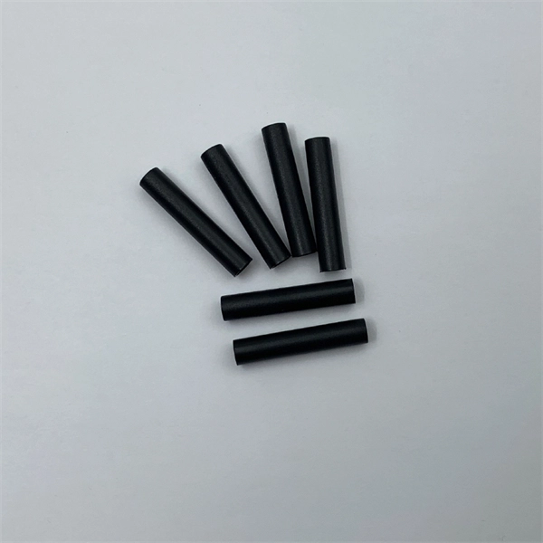
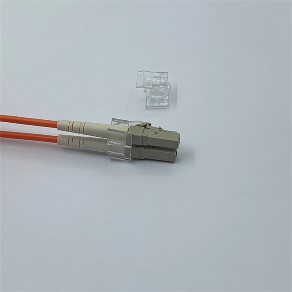
This article provides a step-by-step guide on terminating fiber optic cables, covering essential tools, methods, and best practices. High-speed fiber optic networks form the backbone of modern communications systems. more Audio tracks for some languages were automatically generated. This is where the of the end of fiber and the ferrule that holds it in the connector are polished to give a uniformly flat and clear surface for the best optical performance and minimal signal loss. Optimal performance can be achieved by following the correct process for termination of the fiber circuit—a task which requires the use of a wide range of. Terminating fiber optic cables is a critical skill for telecommunications technicians. Proper termination ensures reliable network performance and minimal signal loss across fiber infrastructure.
[PDF]
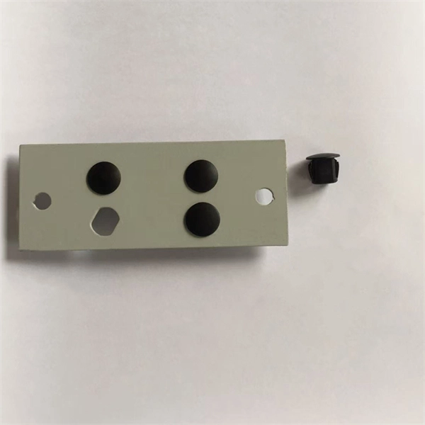
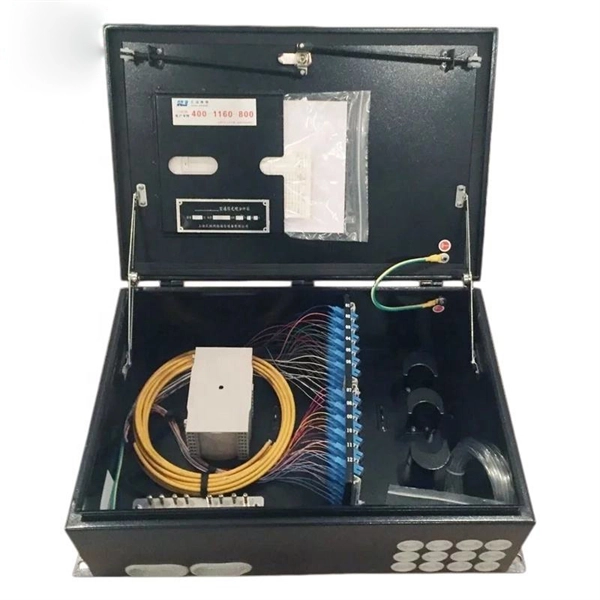
Incoming Distribution Cable: The fiber distribution box receives an incoming distribution cable, which typically carries a bundle of optical fibers. These optical fibers originate from a central source, such as a data center, central office, or distribution point. Fiber Distribution Boxes (FDBs) are critical components in modern telecommunications infrastructure, particularly in fiber optic networks. Minimize the interference of the optical cable access signal to the external environment. The. In the complex architecture of fiber optic networks, the Optical Distribution Frame (ODF) serves as the linchpin for organizing, protecting, and distributing optical signals. Whether in data centers, telecom central offices, or enterprise network rooms, ODFs enable efficient fiber management. An optical cable consists of three primary parts: the core, the cladding, and the protective sheath. Surrounding the core is the cladding, which has a lower refractive index than the core. This complete guide explores everything you need to know about ODFs — from their structure, types, and key components, to installation best practices and modern design trends. Whether you're building a central office, data center, or FTTx distribution network, understanding the right ODF.
[PDF]
In telecommunications, a base station is a fixed transceiver that is the main communication point for one or more wireless mobile client devices. It further connects the device to other. A communication base station is composed of a computer room, base station, antenna, feeder line (transmission line between transmitter and antenna), and supporting equipment. The antenna is at the top of the signal tower, and below the tower is a computer room. Along with increased capacity demands driven by the explosion of cloud and connected device growth, engineers need interconnects that enhance the design. A base transceiver station (BTS) or a baseband unit (BBU) is a piece of equipment that facilitates wireless communication between user equipment (UE) and a network. UEs are devices like mobile phones (handsets), WLL phones, computers with wireless Internet connectivity, or antennas mounted on. Fiber Optic Cables: High-speed fiber optic cables connect the BBU to the RRUs (RE part). Signal Transmission: The optical signals carry data, control, management, and synchronization information. Topology: The BBU and multiple radio heads can be connected in cascade or star configurations. The rise. The design investigates the possibilities of Free-Space Optical (FSO) communication systems and MilliMeter-Wave (MMW) technologies operating at 60. Although these technologies are highly effective and have a high throughput, they are nevertheless vulnerable to weather phenomena like rain.
[PDF]
The Open Systems Interconnection (OSI) model is a developed by the (ISO) that "provides a common basis for the coordination of standards development for the purpose of systems interconnection." In the OSI reference model, the components of a communication system are disting.
[PDF]
An optical fiber, or optical fibre, is a flexible or plastic that can transmit from one end to the other. Such fibers are widely used in, where they permit transmission over longer distances and at higher (data transfer rates) than electrical cables. Fibers are used instead of metal because signals travel along them with less and are immune to.
[PDF]