Digital Diagnostic Monitoring (DDM) can monitor parameters of the optical module regularly and generate alarms when parameter values exceed thresholds. By using DDM, you can detect issues early to maintain network stability. When you configure the DDM function, follow these notes. Optical Module Monitoring & Troubleshooting 2026 – network-switch. com Digital Diagnostics Monitoring (DDM), also known as Digital Optical Monitoring (DOM) or Diagnostic Monitoring Interface (DMI), is a standardized feature defined by SFF-8472 that allows network devices to monitor real-time optical. Digital Diagnostic Monitoring (DDM), also known as Digital Optical Monitoring (DOM), is a key feature in modern optical transceivers. It can provide the host with real-time data about the module's internal operating conditions, including parameters such as voltage. Digital Diagnostics Monitoring (DDM) is a feature used in optical transceiver modules that enables you to view real-time information about transceivers, such as optical output and input power. For information about which F5 ® transceiver modules support DDM, see F5® Platforms: Accessories. It is an intelligent function that enables network administrators to monitor the transceiver's operational parameters in real time. DDM is not merely a feature; it is an industrialized standard.
[PDF]
Optical data couplers are essential components in modern fiber optic networks. They enable the connection and distribution of light signals between fibers, facilitating high-speed data transmission over long distances. As digital communication demands grow, these devices become increasingly vital. Explore the role, types, and applications of fiber optic couplers in telecommunications and data networks in our in-depth article. They serve an essential role in managing the flow of light. A coupler is an optical device that combines or splits optical signals. Couplers can be used to split an optical signal into multiple signals, combine multiple signals into a. The same kind of device is useful in fiber interferometers, also for combining two inputs. (Note that polarization issues might occur. Unlike active devices like switches or transceivers, couplers require no electrical power to function.
[PDF]
There are several factors that can impact the cost of a dedicated internet line. Some of them are out of a customer's control, but some are not. Understanding these factors can help businesses make informe.
[PDF]

At Least Three to Six Feet Away: A commonly suggested distance for minimizing RF exposure is three to six feet (approximately 1-2 meters) from your bed. If possible, aim for six feet or more, especially if you are sensitive to electromagnetic fields (EMFs). The safe distance from a WiFi router depends on the router's power and the level of exposure you are comfortable with. Here are some general guidelines: Minimum Distance: Experts recommend maintaining at least 10 feet (3 meters) from a WiFi router to reduce radiation exposure significantly. Ideal. Keep the router away from high-traffic areas like bedrooms, nurseries, or places where you spend long periods. We typically recommend at least 10 feet away from where you spend most of your time. Instead, place it in a location where it can still emit sufficient coverage but minimize unnecessary. While there are no strict guidelines, most experts recommend keeping a reasonable distance between your WiFi router and sleeping area. Some studies have pointed to a higher risk of sleep disturbance, decreased cognitive function, and even potentially cancer with prolonged proximity to WiFi radiation. Dual-band routers emit signals on 2. At these distances, RF exposure drops to low or minimal levels while maintaining reliable connectivity. For maximum protection during sleep, position your router.
[PDF]
The Americas Region Caribbean Ring System (ARCOS-1) is a of 8,400 kilometers that extends between the, the, the, the,,,,,,,,,,, and. Because of its length, it was divided in two phases: Phase 1 being in service since September 2001 and Phase II since March 2002. The cable system wa.
[PDF]

A fiber pigtail is a short optical fiber cable with a connector pre-installed on one end and a bare fiber on the other. It acts as a bridge between optical fibers and devices, making it a vital part of network termination, splicing, and patching processes. In the world of fiber optic communications, reliability and precision are everything. As networks scale to support FTTH rollouts, 5G base stations, and hyperscale data centers, the way fiber is terminated and managed at every endpoint can determine whether a project succeeds or fails. One component. Executive Summary: A fiber optic pigtail is one of the most commonly specified yet least understood components in structured cabling. Get the wrong connector type, the wrong polish, or skip proper fusion splicing technique—and you're looking at elevated signal loss, increased back reflection, and a. ■ What is a fiber optic pigtail cable? A pigtail fiber indicates a short length of optical fiber cable that has a pigtail connector (for example, SC, FC, ST, LC, etc. ) fitted on one end and the other end undressed (for connection through fusion or splicing) to the main fiber optic cable. What does fiber optic pigtail mean? A fiber optic pigtail works like a bridge between two different connection methods. It is usually suitable for field termination using a mechanical or fusion splicer.
[PDF]

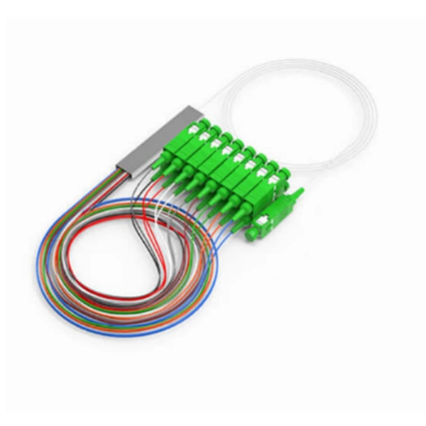
Understanding how to properly place and use an optical splitter is essential for optimizing signal quality and ensuring seamless data transmission. Let's explore the best practices for deploying this crucial component. What is An Optical Splitter?. A fiber optic splitter is a passive optical component that divides a single incoming optical signal into two or more outgoing signals, or combines multiple incoming signals into one. Unlike active devices (which require power), splitters operate without electricity, relying solely on the physics of. Where splitters are placed in the network can make significant impacts on fiber counts, network cost and deployment time and operational steps, such as customer onboarding and maintenance. One important note is that splitting architectures should be seen as tools that can be mixed and matched to. In the realm of optical communication networks, the optical splitter serves a vital role in dividing and distributing optical signals efficiently. You use optical couplers and splitters to split or join signals in fiber networks. These devices help you control light signals well. You can also use them to join light from. This guide will demystify this pivotal passive device, exploring its types, working principles, and how it seamlessly integrates with optical transceivers to bring high-speed internet to your doorstep.
[PDF]


