BARCELONA, Spain, March 6, 2025 /PRNewswire/ — At the Mobile World Congress 2025 (MWC 2025), Huawei launched the StarryLink optical modules, designed to enhance network experiences with “3S” quality (Spanning, Stable, Secure). This announcement occurred during the data center session titled. The global optical transport market returned to growth mode in 2025, climbing 10% year over year to reach $16 billion, according to new data from Dell'Oro Group. The market, projected to reach $14. 7 billion in 2025, is forecast to.
[PDF]
Optical modules have a series of components inside, some of which have received attention from standards development organizations. In many cases, the baud rate of the optical interface does not equal the baud rate of the electrical interface. In these cases, a gearbox is used within the module to convert between the two rates. For example if the module supports 4 x 25 Gb/s electrical inputs and 2 wavelengths of 50 Gb/s optical inte.
[PDF]
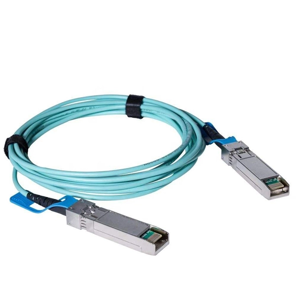
The transceiver is available as a mini-GBIC form factor, making it ideal for environments that require many fiber connections by taking up less space in your cabinet and/or computer room. Compatibility in your network is everything, and the Intellinet SFP Transceiver Module delivers. Use it with any Intellinet SFP equipped network switch or any other MSA-compliant, SFP-enabled switch. And since the Intellinet SFP transceiver module is set to broadcast the vendor on GLC-LH-SM, compatibility to your Cisco gear is provided. No need to power down your LAN switch in order to install or remove the transceiver. This makes it very convenient and easy for you to make adjustments to your network that allow your business to keep pace with the changing demands of the market.
[PDF]

There are a total of 113 Optical Products Manufacturers in Peru as of August 15, 2024. (Google Earth) file formats. Identify and compare relevant B2B manufacturers, suppliers and retailers Max. The company, Opeluce Eye Clinic, specializes in comprehensive care for ophthalmological issues, utilizing advanced diagnostic and treatment technologies for ocular diseases. Their expert ophthalmologists and. To help you choose the best partner, this article will analyze and introduce 10 companies in the optical transceiver industry chain for you. Armotec is a prominent Peruvian company specializing in high-tech measuring instruments, including optical sensors like photoelectric sensors. They offer a variety of products and emphasize their ability to meet the needs. After gathering significant public information from various online sources and conducting relevant analysis and comparisons, we have compiled a list of the leading optical transceiver manufacturers based on market share. 63% increase from 2023. We are dedicated to helping you build, connect, protect and optimize your network. Topstar focuses on R&D and has our Top-trans” brand SFP/SFP+/XFP+QSFP/CFP/QSFP28 series of modules, we offer 24*7 hours online service.
[PDF]
An optical module is a typically hot-pluggable optical transceiver used in high-bandwidth data communications applications. Optical modules typically have an electrical interface on the side that connects to the inside of the system and an optical interface on the side that connects to the outside world through a fiber optic cable. The form factor and electrical interface are often specified by an interested group using a (MSA). Optical modules can either plug into a front pa.
[PDF]
We offer a wide range of OEM-compatible optical transceivers & cables, ensuring reliable, high-speed connectivity. The transceiver consists of three sections: a Cooled EML laser transmitter, a APD photodiode integrated with a trans-impedance preamplifier (TIA). As a professional optical transceiver manufacturer, Innoptical offers an extensive assortment of optical transceivers to fit your requirements. Ranging from low-data rate to 800 GB, our transceivers cover types of SFP, SFP+, SFP28, SFP56, QSFP+, QSFP28, QSFP56, QSFP-DD, OSFP, GPON OLT transceivers. Product Specifications/Features SFP Optical Transceivers are hot-swappable, compact media connectors that provide instant fiber connectivity for your networking gear. They are a cost effective way. The optical transceiver is designed for use in 100/155Mbit/s data links. It provides the SC. The LS-SM312G-40C SFP transceivers are high performance, cost effective modules supporting data rate of 2. 5Gbps and 40km transmission distance with SMF. By seamlessly integrating advanced silicon photonics, ultra high speed circuit and packaging designs, Hyper Photonix offers a comprehensive range. Through lean management, manufacturing and our Source Lean Quality (SLQ) system, we run our world-class operation at maximum efficiency, identifying and eliminating waste in our processes to create more value for our customers. Our technical expertise in R&D runs deep with manufacturing process.
[PDF]

Based on typical issues encountered with optical modules in daily switch applications, this document summarizes basic troubleshooting steps for resolving common faults: 1. Check compatibility between the optical module and switch. The BERT-1102 is an 8-channel PPG and Error Detector for the design, characterization and manufacturing test of optical transceivers and opto-electrical components with symbol rates up to 28 GBaud in both NRZ and PAM4 formats. With scalability and exceptional signal fidelity, it is a cost-effective. First, the transmission class of the optical module fault investigation and solution method This type of optical module failure mainly includes port not UP, port status is UP but do not receive or send messages, port frequently up or down and CRC error. Specific troubleshooting methods and. e PARALLEX® Chassis. EED428 can check 4 channels electrical data from 22. A half-rate input clock is required and it can be daisy-chained to the Pattern Generator a d additional modules. Run the display esn interface command to check whether the optical module is a Huawei-certified one. If the Certified field. As core components of optical communication systems, the proper installation and use of optical modules directly impacts network stability. Combining hardware principles with practical experience, it.
[PDF]
In today's data-driven world, high-speed optical modules (e., 100G/400G/800G) are the backbone of modern networks, enabling ultra-low latency and massive bandwidth for data centers, telecom, and enterprise applications. However, their performance hinges on proper deployment. nd Latency variation are very important in applications requiring accurate timing (e (PAM-4 or Coherent), require complex digital signal processors (DSPs) in optic itional EEPROM data content for propagation del ss C. 2” pluggable : 2% of the cTE budget ITU-T G. 2 allocated for Class C A. 20”. This article helps trading engineers and network architects select an ultra low latency SFP that fits 10G/1G optics needs while minimizing added propagation and serialization delay. A solution for accurately measuring the Latency of PAM4 optical modules is required. Potential source of time error in complex digital parts of pluggables. Higher bit rates (50 Gb/s and higher) and. Transceiver latency is a key spec in enterprise fiber optic networks especially in financial institutions. It is the one of the few variables that can be optimized since fiber path delay is fixed. However, their performance hinges on proper deployment and maintenance.
[PDF]

800G OSFP DR8/DR8+ (Siph) Product Features 1. Optical Interface Protocol: IEEE 802. 3cu 8X 100GBASE-DR 2. Form Factor: OSFP MSA 4. Power Consumption: <18. FS 400G QSFP-DD module solutions featuring high-performance, high-bandwidth, and cost-effectiveness, are ideal for 400GbE and data centres. QSFP (Quad Small Form-Factor Pluggable) optical modules emerged to meet this demand, becoming a pivotal technology for data center interconnects due to their compact size and exceptional performance. From the initial 40G to today's 800G, the QSFP family has continuously evolved, driving the. Cisco QSFP-DD and OSFP 800G ZR/ZR+ digital coherent optics modules enable 800G traffic over amplified Dense Wavelength-Division Multiplexing (DWDM) links up to 120 km for 800ZR and over 1000 km for 800G ZR+. Explore QSFPTEK's lab through a 360° tour, revealing full transceiver testing. Learn how QSFPTEK provides SMB enterprise and data center network solutions to global customers. Help center for. Your request has been submitted successfully. Our sales manager will contact you soon. High-density 800G OSFP and QSFP-DD transceivers support InfiniBand and RoCE, enabling 100m to 2km transmission via MMF and SMF. Get advice, answers, and solutions when you need them. For general questions, email us at hpestore. com Find an authorized reseller, service provider, or support partner to get a quote.
[PDF]

Never touch the card-edge connectors at the insertion end of the module. Holding the SFP module by its sides, insert the SFP module into the port on the switch. Install or remove optical fibers carefully to avoid damage to fiber connectors. Optical modules are electrostatic-sensitive components;. Small Form-factor Pluggable modules (SFP module) are the workhorses of modern network connectivity, enabling flexible fiber optic or copper links between switches, routers, firewalls, and servers. Whether you're upgrading bandwidth, replacing a faulty unit, or reconfiguring your topology, knowing. You can replace a fan module while the switch is operating, as long as you perform the replacement within one minute. If you cannot perform the replacement within one minute, leave the original fan module in the chassis to maintain the designed airflow until you have the replacement fan module on. This section describes how to install an optical module. The method used to install a copper transceiver module is the same, except that the copper transceiver module connects to a network cable instead of optical fibers. Never look directly into an optical module or the ends of optical fibers. What are SFP+, SFP28, SFP56 HUAWEI WDM replacing the optical module video shows you how to replace an optical module. HUAWEI WDM Documentation: The extraction tool is designed to remove transceivers from.
[PDF]
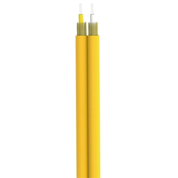
BiDi SFP+ changes the geometry: each module uses a single fiber pair directionally separated by wavelength, so you can run one strand where you previously needed two. One of the most common decisions network engineers face is selecting between single fiber SFP and dual fiber SFP modules. This comprehensive guide explores the differences between single and dual fiber SFPs, their respective benefits, limitations, and use cases—helping you make an informed choice. A single fiber SFP, also known as a BiDi SFP, is designed precisely for this purpose—enabling bidirectional data transmission over a single strand of optical fiber. Unlike traditional SFP transceivers that require two fibers—one for transmitting and one for receiving—a single fiber SFP uses. SFP (Small Form-factor Pluggable) is a compact, hot-pluggable network interface module used to connect network devices (switches, routers, firewalls) to fiber optic or copper cables. An SFP interface on networking hardware is a modular slot for a media-specific transceiver, such as for a fiber-optic cable or a copper. Both transmitting and receiving need one optical fiber to connect. Simplex SFP modules, also known as BIDI transceiver, employs a unidirectional transmission mechanism and have only one port. In practice, that means fewer splice points, smaller patch panels, and less conduit congestion—especially in retrofit buildings.
[PDF]

The LAN-WDM grid consists of four primary wavelengths in the 1310 nm window: These wavelengths were selected to minimize dispersion and allow cost-effective optical component design. LAN-WDM, short for Local Area Network Wavelength Division Multiplexing, is a specialized optical transmission technique that allows multiple high-speed optical signals to be transmitted over a single fiber using closely spaced wavelengths. Originally developed to support high-speed Ethernet. As an essential component of optical fiber communication, optical modules are optoelectronic devices that facilitate the conversion between optical and electrical signals during the transmission process. Operating at the physical layer of the OSI model, optical modules are core devices in optical. In the era of 5G, AI, and high-speed data centers, optical modules serve as the core bridge for converting electrical signals to optical signals (and vice versa), enabling fast, reliable data transmission across networks. It works by dividing light into multiple wavelengths, allowing you to send more data simultaneously over a. With the increasing demand for data centers and high-speed communications, LAN-WDM (LWDM) technology, as an emerging wavelength division multiplexing solution, is gradually becoming the focus of industry attention. This guide delves into the principles, types, applications, and future trends of WDM. Tailored for professionals sourcing solutions from CommMesh, it.
[PDF]
Digital Diagnostic Monitoring (DDM) can monitor parameters of the optical module regularly and generate alarms when parameter values exceed thresholds. By using DDM, you can detect issues early to maintain network stability. When you configure the DDM function, follow these notes. Optical Module Monitoring & Troubleshooting 2026 – network-switch. com Digital Diagnostics Monitoring (DDM), also known as Digital Optical Monitoring (DOM) or Diagnostic Monitoring Interface (DMI), is a standardized feature defined by SFF-8472 that allows network devices to monitor real-time optical. Digital Diagnostic Monitoring (DDM), also known as Digital Optical Monitoring (DOM), is a key feature in modern optical transceivers. It can provide the host with real-time data about the module's internal operating conditions, including parameters such as voltage. Digital Diagnostics Monitoring (DDM) is a feature used in optical transceiver modules that enables you to view real-time information about transceivers, such as optical output and input power. For information about which F5 ® transceiver modules support DDM, see F5® Platforms: Accessories. It is an intelligent function that enables network administrators to monitor the transceiver's operational parameters in real time. DDM is not merely a feature; it is an industrialized standard.
[PDF]