
Equinox blind spot system may show sensor errors or intermittent mirror detection failures. The 'Side Detection Temporarily Unavailable' warning often indicates sensor blockage or malfunction. Check for physical. That “Service ESC” light means your Equinox's Electronic Stability Control system has detected a problem. This is the system that helps keep your car planted and stable when road conditions get dicey, think wet pavement, sharp turns, or icy highways. When it's not working properly, you lose that. I was leaving an event this evening, and as I was stuck in bumper to bumper traffic my car popped up with a message in the display that the Side Detection System was unavailable (2018 Chevy Equinox Premier). And sure enough, the blind spot detection stopped working. Of course this had to happen at. The time now is 12:49 PM. 2025 chevrolet equinox Technical Service Bulletins (TSBs). These sensors may be dirty, obstructed, or experiencing communication problems. track control etc plus random service messages. 1 click faint light on then off. happened all of a sudden. seems to run ok when it. This sub-reddit is dedicated to everything related to Chevy vehicles: driving, racing, collecting, and more. Equinox Blind Spot Sensors - Where are they? Hi! I just bought an equinox 4 days ago, and suddenly my blind spot warning lights in my side mirrors are coming on all the time when there.
[PDF]
The Lightning Pick system is so intuitive and easy to understand that temporary workers can be effective with just a few minutes of training. Complex systems with steep training curves don't fit modern warehousing and order picking n. The Lightning Pick system is so intuitive and easy to understand that temporary workers can be effective with just a few minutes of training. Complex systems with steep training curves don't fit modern warehousing and order picking needs. Also, these systems are highly adaptable, so they evolve along with your business. Light modules are easy to ad. When an SKU must be picked from a specific location, the right indicator turns on to indicate action is required. The picker selects the quantity displayed and confirms the pick by pressing the lighted button. Light-directed picking systems can easily be configured to drive performance make picking more efficient for: 1. Fast, medium and slow velocity SKUs 2. Order picking, kitting and sortation 3. Full and split-case picking 4. Many popular picking methodologies such as zone picking, cluster picking, bucket brigade, batch picking, order consolidation, s.
[PDF]

This SFP module provides 20km transmission distance over single-mode fiber at a nominal wavelength of 1310nm. The transmitter section uses a 1310nm FP laser that is a class 1 laser compliant according to International Safety Standard IEC 60825. A 1310nm optical module lets you move data efficiently through fiber optic communication networks. As part of the O-band (1260–1360 nm), it balances low dispersion, stable performance, and cost efficiency. This makes it widely adopted in data centers, enterprise backbones, and metro access. The transmission distance of optical modules is divided into short distance, medium distance, and long distance. Transmission distances greater than or equal to 30km are considered long-distance transmissions. Light commonly used in optical fiber is 850nm. The GPON OLT SFP transceiver provides an asymmetric 1. 244Gbps upstream and 2. 488Gbps downstream, reaching a link up to 20km over SMF via SC/UPC connector. It can operate at temperatures between -40°C and 85°C. Digital optical monitoring (DOM) support is also present to allow access to real-time.
[PDF]
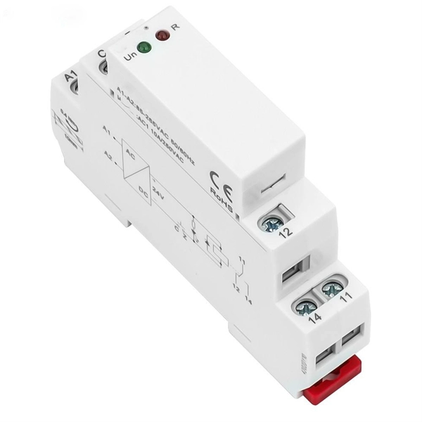
Founded in 1984, Zhejiang Dongya Electronic Co., Ltd specialize in designing, manufacturing and selling high and low-voltage DC contactors, relays, shunts, hydraulic circuit breakers, BDUs and other products. DONGYA is industrial technology Professional design and manufacture dc contactors manufacturers. was established in 1984, with registered capital of USD 1,482,353. We offer dozens of product series and more than 300 models with annual production capacity. Zhejiang Dongya Electronics Co. We have set up.
[PDF]
By providing a physical air gap via photoelectric isolation, this 817 optocoupler board ensures that noise or electrical faults on the load side never reach your expensive processing unit. This voltage level shifter is designed for high-reliability interface driving. Onboard 4-Channel 817 Are Independent:can achieve different voltage control at then same time The output ports are independent of each other. Module Diagram: One Channel of the 4-Channel Optocoupler High-Power Motor Drive Module. Optocoupler Isolation Relay Mo. AC 110V Motor Forward Reverse. The FOD3182 is a 3A output current, high-speed MOSFET gate drive optocoupler. It consists of an aluminium gallium arsenide (AlGaAs) light emitting diode (LED) optically coupled to a CMOS detector with PMOS and NMOS output power transistors integrated circuit power stage. It is ideally suited for. An optocoupler, also known as photo-coupler or opto-isolator, is a component which can transfer an electrical signal across two galvanically¬-isolated circuits by means of optical coupling. Inside the package, an infrared LED on the input side shines onto a phototransistor on the output side. They are sometimes known as opto-isolators, photocouplers, or optical isolators.
[PDF]

Single fiber modules (BiDi) use one fiber for both transmitting and receiving data. This saves space and money. They are easier to set up and give steady communication. They use a thin fiber. Pioneer LX305 only has 1 optical input, can I add another with some kind of splitter? I love my new receiver but I need a second optical input and I'm wondering what my options are in this regard. Can anyone help? Thanks in advance. Edit: Everyone is going to ask this question, so here are my. The single-mode optical fiber is designed and engineered to carry one single light mode in a minimal core diameter. It is specified as the best for especially long-distance applications than multimode fiber. Due to its. The optical module serves as a crucial component in optical fiber communication systems, operating at the physical layer, which is the lowest layer in the OSI model. Its primary function is to achieve optoelectronic conversion by converting electrical signals into optical signals and vice versa. An. There are single-fiber and dual-fiber optical transceivers. How do we choose, and what are their differences and advantages? Let's learn about this! What is a Single-Fiber (BiDi) Transceiver? Single fiber module also called BiDi transceiver or WDM module.
[PDF]

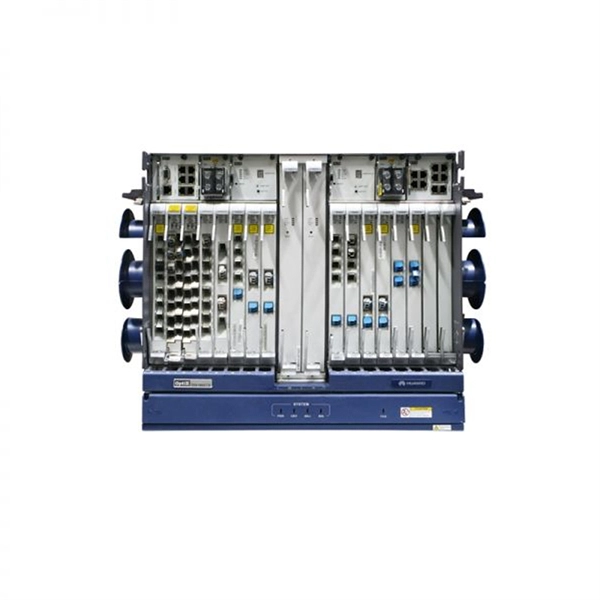
One SFP module is inserted into the switch's SFP port, and another module is inserted into the SFP port of the target device, facilitating data transmission through the fiber optic cable. SFP ports are small hot-pluggable module interfaces typically used for connecting fiber optics or copper cables. They support various transmission rates and distances, including 1G, 10G, and higher speeds. SFP modules can be selected based on the requirements, whether it's single-mode fiber for. An SFP port is a physically small slot in a networking device that accepts an SFP module insert. Most modern networking devices, such as Ethernet switches, servers, routers, network interface cards, and fiber media converters, generally have two or more built-in SFP ports. You may connect different. In plain terms, an SFP port on a gigabit switch is the little plug-in hole that gives the switch physical flexibility — the ability to use fiber one minute and copper the next without buying a different switch. Unlike fixed RJ45 copper ports, SFP ports support both fiber and copper modules, enabling far longer distances, greater flexibility, and improved scalability in enterprise. First, to connect SFP modules with fiber optic cables, ensure that the module type matches the line, as there are different modules for single-mode and multimode fiber. Next, insert the module firmly and securely into the SFP port, then attach the cable to the module using the connector. Switches with SFP ports can.
[PDF]
Explore QSFPTEK 800G OSFP optics price lists and datasheets. The 800G optics provide ultra low latency, low power, and high reliability optical interconnect core components for data centers, AI computing clusters and ISP networks. FS provides an expanding portfolio of 800G OSFP/QSFP-DD solutions featuring high-performance, high-bandwidth, and backward compatibility. The 800G transceiver modules are ideal choice for AI data centers, enterprise networks and service provider networks. Explore QSFPTEK's lab through a 360° tour, revealing full transceiver testing. Learn how QSFPTEK provides SMB enterprise and data center network solutions to global customers. Help center for. Cisco QSFP-DD and OSFP 800G ZR/ZR+ digital coherent optics modules enable 800G traffic over amplified Dense Wavelength-Division Multiplexing (DWDM) links up to 120 km for 800ZR and over 1000 km for 800G ZR+. Our sales manager will contact you soon. High-density 800G OSFP and QSFP-DD transceivers support InfiniBand and RoCE, enabling 100m to 2km transmission via MMF and SMF. This transceiver is compliant with IEEE P802. The built-in digital diagnostics monitoring (DDM) allows. GIGALIGHT 800G QSFP-DD SR8 is a hot-pluggable optical transceiver module designed for 800G SR8 Ethernet links in data centers. It adopts 100G PAM4 and VCSEL technology and can realize 800G data exchange within 100m.
[PDF]

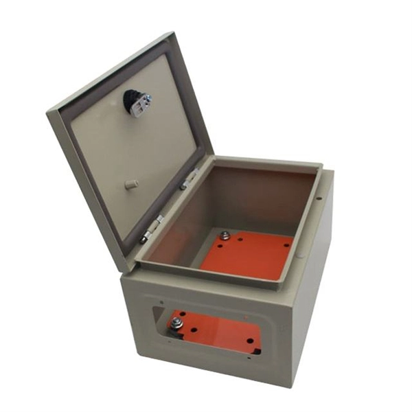
This guide will walk you through the essential steps and best practices for wiring LED modules, with insights from industry-leading models such as the LM Series, SLM Series, LM16 Series, and LM13 Series. WAGO's all-new 2070 Series Through-Board SMD PCB Terminal Blocks provide back-side wiring of LED modules. This new design minimizes on-board LED shadowing and simplifies wiring. 2 to. Watch this video to learn how to set up the Near Module. The Module is a retrofit LED module that can fit most aluminium GU10 housings/frames. Tool required: wire strippers, drilland screw driver and screws 1. Noting metal Box depth, width and face material, choose the suitable spacing and quantity of led module, Carefully choose the acrylic panel, the light-diffusion and permeating of which has great effect on brightness and uniform of. © Copyrights. Control what color your want your LED to be with this RGB LED! On-board resistors make it a breeze to wire up! *This module is part of the KY series of sensors which means that the prints on the board might be mislabelled, do read our notes in the description to understand how to wire it properly. All Rights Reserved Buy LED Modules. element14 Singapore offers fast quotes, same day dispatch, fast delivery, wide inventory, datasheets & technical support.
[PDF]
Click to get your 10G SFP+ transceiver modules from nearby warehouses. Trusted by 260K+ Enterprise Users. Discover the Brocade Compatible 10G SFP+ BiDi Transceiver with 1270nm TX / 1330nm RX, 10km reach, LC SMF, DOM, industrial grade for reliable high-speed networking. Compatible with 10G-SFPP-BXU-I. The LINK-PP LS-BL273310-10I SFP+ transceiver is fully compatible with Extreme 10GB-BX10-U-I. The. FS 10GbE SFP+ module solutions provide a wide variety of 10 Gigabit Ethernet connectivity options for data centers, enterprise wiring closets, Internet Service Providers (ISPs) applications. Trusted by 260K+. Find competitive sfp module prices for various optical transceivers. Our range includes 1. 25G, 10G, and 25G modules with different reach and compatibility. Fiber optic transceiver modules are fiber cable adaptive housings that contain a light source for transmitting data via fiber optic cable as well as a photodiode for receiving fiber optic data. Mounting options include pluggable CXP, QSFP, SFF, SFP, and XFP, surface or through-hole, CFP, 1x9 SC. 10G SFP+ transceivers are available in many different transmitting and receiving types. Users can select the appropriate transceiver for each link to provide the "optical performance" that can be achieved based on the fiber type available such as multi-mode or single-mode optical fiber. Moxa's small form-factor pluggable transceiver (SFP) Ethernet fiber modules for Fast Ethernet provide coverage across a.
[PDF]
The main trade show for the large optical module industry is the Optical Fiber Conference (OFC), that is held annually in southern California. Other prominent shows for the industry include ECOC in Europe and FOE in Japan. OverviewAn optical module is a typically hot-pluggable optical transceiver used in high-bandwidth data communications applications. Optical modules typically have an electrical interface on the side that connects t. There have been multiple variants of the electrical interface of optical modules that have been used over the years. The earliest forms of optical modules had an analog electrical interface. In the transmit dir. Many different forms of optical modulation and multiplexing have been employed in optical modules. The most common modulation technique historically has been or NRZ.
[PDF]

As an important part of fiber-optic communication, an optical module is a photoelectric converter which converts electrical signals into optical signals and vice versa. An optical module works at the physical layer of the OSI model and is one of the core components in the fiber. They mainly consist of optoelectronic components (such as optical transmitters and receivers), functional circuits, and optical interfaces, aiming to achieve the functionalities of optical-to-electrical and electrical-to-optical signal conversion in optical fiber communication. The working. Optical fiber consists of a cylindrical core that propagates light and a concentric cladding that surrounds it. The cladding's refractive index is slightly smaller than that of the core, which confines light within the core and propagates by repeated total reflection at the boundary with the. Broadband Circuits for Optical Fiber Communication, E. Sackinger, Wiley, 2005. Design of Integrated Circuits for Optical Communications, B. High-Speed Digital. The frequency response characterization of these electrical-to-optical (E/O, modulators sometimes integrated with lasers) and optical-to-electrical (O/E, photo detectors and receivers) converters can be important in terms of such parameters as bandwidth, flatness, phase linearity and group delay.
[PDF]
Check the diagnostic information, which shows that the received optical power is low, with a threshold of -3 to -23. 01, currently at -22. Once it exceeds the threshold, an alarm will be triggered. Troubleshoot the link, and if the link is normal, replace the optical module. The receive power of an optical module is too low. Indicates the MIB object ID of the alarm. The device management or driver software has a bug. Use an optical power meter to check whether the transmit optical power of the optical module is normal. Remove and. When an optical module is running on a switch, it is often necessary to read its internal information to check the operating status, including link status, real-time Tx/Rx optical power, and temperature. Verifying module identification also helps confirm coding compatibility between the module and. The optical module on the port generates an alarm. Built into modern SFP/SFP+/ SFP28 /QSFP family modules and standardized by SFF-8472, DDM/DOM exposes real-time values for the module's temperature, supply. This chapter gives a description, severity, and troubleshooting procedure for each commonly encountered Cisco NCS 1001 alarm and condition. When an alarm is raised, refer to its clearing procedure. Default Severity: Critical (CR), Service Affecting (SA) Logical Object: EQUIPMENT The 0/PM [0|1] Unit.
[PDF]

