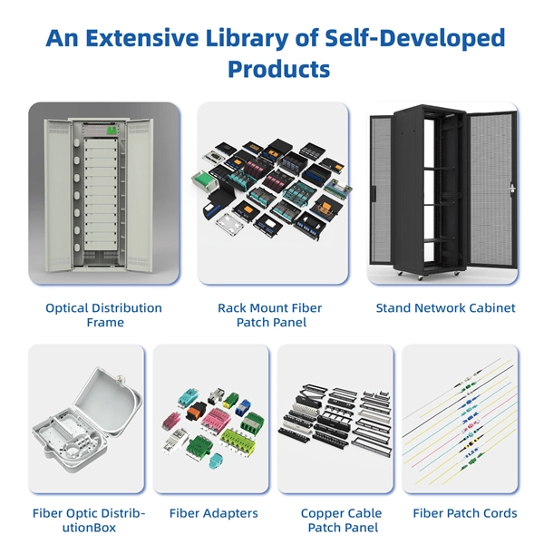
The use of locking cabinets with advanced steel and tamper-resistant designs utilizes physical barriers to limit access to sensitive materials, making them harder to reach for unauthorized individuals. This pressure can cause the gap below server cabinets, which is often 2” or more, to become an air stream between hot and cold aisles. The resulting mix of air reduces the effectiveness of a containment solution. The Cool Shield Magnetic Cabinet Skirt provides an easy fix for this issue. These. Commercial environments have evolved as technology advances, and having a robust cabling infrastructure is crucial for scalability, minimising downtime, and enhancing productivity. Educational institutions are increasingly adopting smart technologies and cloud-based resources, so the foundation of. Many network devices are stored in the cabinets. In order to meet the normal operation of these devices in the cabinets, when the computer room cabinets are full of various cabinets and devices, we need to consider how to place the network cabinets? 1. Network cabinet placement skills (1) Before. A network cabinet is defined as a physically enclosed compartment built to store networking gadgets like patch panels, modems, switches, and a multitude of cables. Network cabinets support large, modular network switches by providing additional space for cable management and side-to-side airflow solutions. Networking cabinets tend to have.
[PDF]

It's called a breaker box, and even though it might not look very exciting on the outside, what's behind that little door is the heart of your home's electrical system. Bottom Line Up Front: Your home's distribution box (electrical panel) is typically located in the basement, garage, utility room, or mounted outside near your electrical meter. To find it quickly, look for a rectangular gray metal box about the size of a medicine cabinet, often positioned close to. Electrical panel boxes, aka breaker boxes, can be on a wall in an out-of-the-way area of your home. You can find electric panels inside cabinets, behind refrigerators, or inside clothes closets in older homes. Current National Electrical Codes (NEC) allow none of these locations. Electrical panels. The electrical panel is the central hub that distributes electricity throughout the house. Knowing where to find your electrical panel in your home helps in case of emergencies and routine maintenance. Panels are commonly found in garages, basements, utility rooms, and outdoor walls. Understanding how your electrical panel works can help you troubleshoot issues, perform basic maintenance, and know when to. When something electrical goes wrong in your home—like a tripped circuit or sudden power outage in one part of the house—most people instinctively head to that gray metal panel, often hidden in a basement, utility closet, or garage. Having the breaker box.
[PDF]
Unlike traditional metal-style reels, MARS is a lightweight, modular system constructed of an impact modified polymer that is easily transported. It is ideal for applications where cable needs to be deployed and reeled in quickly and stored efficiently. OCC's Modular Advanced Reel System (MARS ®), the industry's first lightweight cable deployment reel system, is designed specifically for the demanding needs of harsh-environment fiber optic installations. The dual take-ups are designed to work independently from line controls, therefore providing an easy adaptation and a fast plug & play installation to any line.
[PDF]

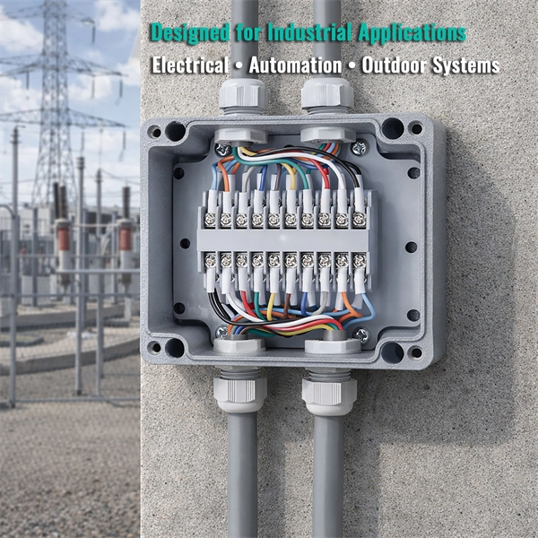
In this article, we will discuss the wiring diagram for a typical 6 terminal junction box, which is commonly used in residential and commercial buildings for a variety of applications. Learn how to wire a distribution box step by step! This video shows real on-site footage of electrical installation, demonstrating safe and standardized wiring methods used by professionals. Wiring Direction: Wiring between the main circuit breaker and each branch circuit breaker in the box generally. In this guide, we'll break down everything you need to know to install a distribution box correctly and confidently. Choose the right box based on environment (indoor/outdoor), load capacity, and durability. Check for proper IP/NEMA ratings and material quality. Ensure safe placement: install in. It is the policy of the Company to serve all its customers in an orderly manner and assist in securing a more beneficial use of electricity. The “Xcel Energy Standard for Electric Installation and Use” contains the requirements and uniform standards necessary to achieve this policy. Uniform. An electrical panel box, also known as a breaker box or a distribution board, is a crucial component of any electrical system. It serves as a central hub for distributing electricity throughout a building, ensuring that power is delivered safely and efficiently to all the required locations. The 6 terminal junction box wiring diagram provides a visual representation of how the various wires and.
[PDF]
Scattering accounts for the greatest amount of attenuation in a fiber cable, between 95 and 97 percent. Light traveling through the fiber interacts with the densities as shown in the light and is then partially scattered in all directions. Fiber optic cables have many advantages, but one of the downsides just like with copper cable, is that it can experience what is called attenuation. Attenuation refers to the loss of light as it travels down the fiber. This can be due to a variety of factors: scattering and absorption, intrinsic. This attenuation is inevitable, so the smaller the attenuation value, the longer the transmission distance of the same optical power. The better the quality of this fiber patch cable. It indicates the amount of signal reflected back. At TREND Networks, we are frequently asked how much loss is allowed when conducting testing on fiber optic cabling. Unfortunately, it is not a simple answer and depends on several factors. So how do you determine acceptable loss? When testing fiber optic cabling, determining acceptable loss is. Understanding fiber loss is vital in maintaining a reliable, efficient network. Understanding it is crucial for anyone involved in data centers, telecommunications, or enterprise networking. Here are the details and instructions about each field and how they contribute to the calculation: 1. Attenuation Coefficient (dB/km): This value represents the inherent signal loss per kilometer of.
[PDF]
The attenuation value of a fixed optical attenuator is actually its insertion loss. A VOA has an adjustment range. An optical attenuator, or fiber optic attenuator, is a device used to reduce the power level of an optical signal, either in free space or in an optical fiber. Optical attenuators are commonly used in. 📦 For purchasing, use the RP Photonics Buyer's Guide for optical attenuators. It provides an expert-curated supplier directory, buyer-focused technical background information, and structured selection criteria to support professional procurement decisions. It primarily ensures the power or amplitude of a signal is lowered without significantly distorting its waveform. A fixed optical attenuator attenuates the optical power in an optical fiber link by a fixed value, for example, 3 dB, 5 dB, 10 dB, or any value. An optical attenuator is a passive device that reduces optical power in a controlled way without changing the signal format. If a transmitter outputs +3 dBm and.
[PDF]
Send us your information to receive a customized quote from our dedicated customer service team. •Compact benchtop instrument for all-in-one operation optic components quickly and accurately. The system has a or LED source for multi-mode applications. With a dual two wavelengths in less than 1 second. ILM-100 system comes integration into test systems. Insertion loss is measured by utilizing the built-in, stabilized LASER or LED source in combination with the precision optical power meter. Using the OP815, dual wavelength insertion loss (IL). Desktop Insertion Return Loss Tester with color screen has stable and reliable performance, which integrates stable light source, high-precision power meter, insertion loss meter and return loss meter into one multifunction instrument. Each SMLP5-5 Kit includes an OLS4 quad Optical Light Source and OPM5 Optical Power Meter. OLS4 is an integrated two-port LED (850 and 1300nm) and laser (1310 and 1550nm).
[PDF]

Managing optical attenuation helps keep your signal safe. Clean your optical connectors so you do not lose. Optical Signal Attenuation is the single greatest factor limiting the distance and performance of your network. Understanding it is crucial for anyone involved in data centers, telecommunications, or enterprise networking. This guide will demystify signal loss, explore its causes, and show you how. In high-speed environments, where the optical link budget is measured in fractions of a decibel, diagnosing and eliminating unexpected loss is the network engineer's most critical task. This field guide provides a systematic, step-by-step approach to troubleshooting and resolving the most common. Signal loss in Fiber Optic networks can make data slow. It can also break your connection. You should fix it fast to get speed and stability back. > You can solve this with simple steps. Signal Degradation (Loss of Light) When the signal quality degrades, it could be a sign of attenuation or excessive loss in the system. The signal might become weaker, resulting in slower speeds or dropped connections. -. Fiber optic networks are celebrated for their speed and reliability, but even the best systems can encounter problems. When issues like signal loss, slow speeds, or intermittent connectivity arise, systematic troubleshooting is key. Things like impurities in the fiber core and reflections at the core-cladding edge cause this drop.
[PDF]

Normal WDM (sometimes called BWDM) uses the two normal wavelengths 1310 and 1550 nm on one fiber. Coarse WDM provides up to 16 channels across multiple transmission windows of silica fibers. Dense WDM (DWDM) uses the C-Band (1530 nm-1565 nm) transmission window but with denser. In fiber-optic communications, wavelength-division multiplexing (WDM) is a technology which multiplexes a number of optical carrier signals onto a single optical fiber by using different wavelengths (i., colors) of laser light. This technique enables bidirectional communications over a. This section contains examples of wavelength division multiplexing (WDM) circuits. Wavelength division multiplexing is a method of modulating multiple signals at different wavelengths (channels) to transmit them on a single waveguide or fiber. This guide delves into the principles, types, applications, and future trends of WDM. We explain the different types of WDM and how WDM-enabled optical networks can help your business. The concept involves sending multiple independent data streams down a single strand of fiber, much like transforming a single-lane road into a. Wavelength Division Multiplexing (WDM) is a technique in fiber-optic communication systems that enables multiple optical signals with different wavelengths to be combined, transmitted, and separated over a single optical fiber. This allows multiple channels of data to be transmitted simultaneously.
[PDF]
This Quick Reference Guide is intended to provide highlights of OPGW installation instructions needed in the field. Please review the document (WI-0298 Rev 1) before proceeding with. Describe the system used for installation and delivery of OPGW fibre optic cables. - SCOPE This document covers all the activities usually performed by PRYSMIAN for on-site installation of OPGW fibre optic cables, including transport, installation, accessory assembly, verification of optical. This manual is formulated in accordance with IEEE 1138 - 2008 and IEEE 524 - 1992, etc. OPGW has dual functions of aerial ground wire and fiber communication. To. The OPGW cable installation process 2 involves careful preparation, precise laying and stringing, installation of necessary hardware, and thorough testing. I have seen that following these steps makes the installation work well and ensures high performance and reliability. I once worked on a. Discover the perfect fiber training course for your career path. This fiber optic training course is designed for those who specify, design, install, construct or maintain aerial Optical Power Ground wire systems in investor-owned, Electric Power Utilities, REAs, Co-operatives, and municipal power. Optical Ground Wire (OPGW) is a crucial component for reliable communication in power transmission systems. OPGW fiber optic cable is a unique type of cable that.
[PDF]
This video shows real on-site footage of electrical installation, demonstrating safe and standardized wiring methods used by professionals. more Learn how to wire a distribution box step by step! This video shows real on-site footage of. Understanding the wiring diagram of an electrical panel box is essential for electricians and homeowners alike, as it allows them to troubleshoot any electrical issues, carry out repairs, or make additions to the system. The electrical panel box wiring diagram provides a visual representation of. A distribution box is the heart of any electrical system. It takes the incoming power and safely distributes it to different circuits throughout your building. Whether in a home or an industrial facility, this box keeps your electrical setup organized, functional, and efficient. However, the key to. In this video, we'll walk you through the process of wiring a home distribution box with a detailed connection diagram. It has three categories: residential, commercial and industrial electrical distribution boxes, all of which play important roles in their respective electrical. It is responsible for distributing electricity throughout a building, ensuring that each circuit receives the proper amount of power. To understand how a breaker box works, it is helpful to have a wiring diagram that shows the connections between the various components. At the heart of a breaker.
[PDF]
The process involves a combination of national infrastructure, local engineering, and property-level setup. In this guide, we'll break down the fiber installation process from start to finish and explain key components such as fiber cabinets, flower pods, ducting, and ONT. Our fiber optic installation process covers everything from planning and preparation to termination and testing. But how does it work? Keep reading to find out. What Is Fiber Optic. This fiber optic installation method statement covers the termination of fiber optic cables with patch panel, network distribution cabinet NDC and door junction box but can be applicable for any kind of network installations. Roles and Responsibilities: The electrical manager shall be responsible. Setting up a fiber optic network requires careful planning and execution. This guide provides a step-by-step overview of the installation process, ensuring a smooth transition from traditional cabling systems. Introduction Installing a fiber optic network can seem daunting, but with the right. This beginner-friendly guide will walk you through the step-by-step process of fiber optic cable installation for each method, highlighting best practices, tools, and considerations. Unlike traditional copper wiring, fiber optics installation provides superior bandwidth, faster speeds, and resistance to electromagnetic interference.
[PDF]
Buy Panduit LabelCore Fiber Optic Cable Identification System Self-Laminating Laser/Ink Jet Labels at SHI. See detailed specifications and benefit from expert support. Shop IT hardware and software products with SHI now!. Indoor & outdoor fiber cable high visibility markers, id labels, printers, warning signs & posts, cable id sleeves and more for fiber optic applications. Check each product page for other buying options. Need help? Explore write-on fiber optic cable tags with self-laminating protection. Keep your cables organized and clearly labeled with writable identification solutions. The Multilink cable markers utilize a simple and quick installation that allows the installer to simply wrap the marker around the selected cable without the need for special tools or adhesives. The UV stabilized body will not degrade in outside applications and a variety of colors allows easy. According to research conducted by industry experts that shows network failures cost businesses the equivalent of five thousand dollars per minute. If technicians aren't able to quickly recognize the correct cable, these minutes can add up quickly. The TIA/EIA-606-A standard has created a unified system that specifies a "common" method of labeling the complete telecommunication infrastructure. PANDUIT Labeling Software packages include all label formats for quick and.
[PDF]