This guide covers everything: what fiber optic pigtails are, how they differ from patch cords, which connector and polish type to specify, how to choose between mechanical and fusion splicing, and the real-world applications where pigtails are the right call. In this guide, we cover the basics of fiber optic splicing, how to perform splicing using two different methods, and finally some best practices to perform good fiber splicing. What is Fiber Optic Splicing and Why is it Needed? – #1. Whether you're building out an ODF. Think of a fiber optic cable splice as the seamless stitching that keeps data flowing through the delicate threads of a network—like a master tailor joining fabric with precision. Whether repairing a broken cable or extending a fiber run, fiber optic splicing ensures light signals travel. Fibre optic splicing is an essential skill in the world of modern telecommunications, offering a reliable method to connect optical fibres for seamless data transmission. As the demand for high-speed internet and robust communication networks continues to grow, learning to splice fibre optics is. In this guide, you will find a chronological description of the fusion splicing process, the principal technical standards, and answers to the real-life questions network engineers and procurement teams may have. Therefore, we will also touch on cost factors, risk management, and best practices in.
[PDF]

RCCBs (Residual Current Circuit Breakers) should be installed in key areas of your home's electrical system for maximum safety. The best place to install an RCCB is in the distribution board (DB box), which controls the electrical circuits throughout your home. This location ensures that the RCCB protects the entire electrical system by monitoring the current flow throughout. For added protection, you can also. A residual-current device (RCD), residual-current circuit breaker (RCCB) or ground fault circuit interrupter (GFCI) is an electrical safety device, more specifically a form of Earth-leakage circuit breaker, that interrupts an electrical circuit when the current passing through line and neutral. The primary function of an RCD is to monitor the electrical current flowing in a circuit and quickly disconnect the power supply if it detects an imbalance current (leakage of current to ground) between the live and neutral conductors. An RCD is essentially a current-operated ELCB and is commonly. RCCB Definition: A Residual Current Circuit Breaker (RCCB) is defined as a safety device that detects and interrupts a circuit when there is a leakage current to the ground. It can swiftly disconnect the circuit when a fault current happens and prevent wiring damage. In this article, we explain what an RCBO is and how it.
[PDF]

Connect all three phases and the neutral wire to the input of the residual-current device. An overcurrent circuit breaker is connected at the output to each phase. It is an electrical protective device that protects electrical circuits and devices from some electrical faults such as leakage faults, electrical shock, current unbalance due to equipment failure, etc. It works on the principle of sensing residual current which is why it is called a residual. Distribution board is a safe system designed for house or building that included protective devices, isolatorswitches, circuit breaker and fuses to connect safely the cables and wires to the sub circuits and final sub circuits including their associated Live (Phase) Neutral and Earth conductors. A residual-current device (RCD), protects the user of the installation against electric shock. Therefore, not only the efficiency and reliability, but also the proper connection of this device is important. Make sure you have watched the linked video below on how to strip and prepare wires and cables for termination before you do any wiring:. more Audio tracks for some languages were automatically generated. This guide provides a detailed, professional procedure for installing a Residual Current Circuit Breaker (RCCB)—a device essential for protecting people from the severe danger of electric shock. The steps outlined here are fundamental to ensuring the RCCB functions correctly as a life-saving.
[PDF]
FOCS systems can measure currents up to 700 kA. They offer a practical alternative to traditional Hall-effect sensors, using a lightweight, clamp-on design that allows installation without opening bus bars — reducing time and complexity. A fiber-optic current sensor (FOCS) is a device designed to measure direct current. Utilizing a single-ended optical fiber wrapped around the current conductor, FOCS exploits the magneto-optic effect (Faraday effect). The result is exceptional accuracy and reliability. Based on the magneto-optic effect, FOCS can measure uni- or bidirectional DC ering signal disturbance immunity available for complex industrial processes. It is unaffected by stray magnetic fields at the plant, s. The FS205 is a high precision DC high current measurement device based on the Faraday Magneto-optical Effect and the Ampere Loop Theorem. The sensing optical fiber is fixedly mounted on the high current busbar through a skeleton and forms a closed optical fiber loop. They are immune to electromagnetic interference (EMI) and do not suffer from magnetic saturation, which improves accuracy, simplifies installation, and enables reliable digital. A fiberoptic sensor that uses diverse fiber units to support various applications in virtually any environment. These are reliable and easy-to-use devices that have high power, can automatically adjust to real-time conditions, and have a straightforward display that eliminates any guesswork.
[PDF]
This guide provides a detailed, professional procedure for installing a Residual Current Circuit Breaker (RCCB)—a device essential for protecting people from the severe danger of electric shock. The steps outlined here are fundamental to ensuring the RCCB functions. It is an electrical protective device that protects electrical circuits and devices from some electrical faults such as leakage faults, electrical shock, current unbalance due to equipment failure, etc. It works on the principle of sensing residual current which is why it is called a residual. Distribution board is a safe system designed for house or building that included protective devices, isolator switches, circuit breaker and fuses to connect safely the cables and wires to the sub circuits and final sub circuits including their associated Live (Phase) Neutral and Earth conductors. Residual-current devices, commonly referred to as RCDs, are used in many practical applications. They can be found in fuse boxes, electrical switchgears or industrial machine control systems. Therefore. To wire an RCD fuse box correctly, start by reviewing the diagram to identify each circuit and its corresponding components. Understanding the layout helps prevent mistakes and ensures safe wiring. floor in a multi storey building. The Sub distribution board is connected and supplied from the Main Distribution Board through different wires and cables rated.
[PDF]

The six-phase sequence current protection tester is an advanced device used to verify complex protection devices. Its core principle lies in the simultaneous output of six independent current and voltage signals to simulate various normal and fault conditions in a power system. It not only supports. In the complex world of power system protection, the Six Phase Relay Protection Test Set has emerged as an indispensable tool for engineers and technicians. These advanced devices play a critical role in verifying the reliability and accuracy of protective relays, ensuring the safe operation of. The CMC 356 is the universal solution for testing all generations and types of protection relays. Its powerful six current sources (three-phase mode: up to 64 A / 860 VA per channel) with a great dynamic range, make the unit capable of testing even high-burden electromechanical relays with very. JBC-806tester can simultaneously outputstandard six-phase current and six-phase voltage with 30A/phase current and 125V/phase voltage. With its six-phase output, this tester provides comprehensive testing capabilities, making it an essential instrument for ensuring the. nation in general. Not influenced by load, they contribute to protection speed and sensitivity. However, sequence components are present for a range of conditions, not only faults: open pole, load and line unba ance, breaker pole scatter, and current transformer ratio errors and saturation, to name.
[PDF]
The agreement, signed Tuesday, June 17, aims to develop a resilient, high-capacity national backbone network to strengthen the country's digital transformation. The project's first phase, scheduled over the next six months, will connect the cities of Plumtree, Bulawayo, and Livingstone. VICTORIA, British Columbia, May 06, 2026 -- (BUSINESS WIRE)--Vecima Networks Inc. (TSX: VCM) announced today that leading telecommunications operator Elisa has deployed Vecima's Entra EXS1610 All-PON™ Shelf for 10G Fiber-to-the-Home (FTTH) services for its subscribers in Estonia. In Estonia's. Zimbabwe is advancing its fiber optic infrastructure through a new partnership between PowerTel Communications—a subsidiary of the national electricity company—and Paratus Zimbabwe. The group, in its year to February 2025 financial statements, said the. PowerTel and Paratus Zimbabwe, a division of the Paratus Group, signed a significant agreement on Monday to establish a new high-capacity national fibre network throughout Zimbabwe. Zida said this week the telecoms sector was rapidly. At the heart of a point-to-multi-point or passive optical network (PON) is the optical line terminal (OLT). Modern OLTs offer communication service providers (CSP) the ability to launch multigigabit services to tens of thousands of subscribers from a single location or just ten. Fiber-to-the-home.
[PDF]

The term laser diode refers to a semiconductor device that emits laser light when an electrical current passes through it. Unlike regular LEDs that emit incoherent light, laser diodes produce coherent light—meaning the light waves are all aligned in phase and travel in a narrow . A laser diode (LD, also injection laser diode or ILD or semiconductor laser or diode laser) is a semiconductor device similar to a light-emitting diode in which a diode pumped directly with electrical current can create lasing conditions at the diode's junction. These devices are currently used in the fields of telecommunications and medicine and in industrial cutting and welding applications. This article discusses the characteristics common to laser. Laser diodes produce coherent light by stimulating photon emission at a semiconductor junction. Operational Mechanism: Laser diodes create light through stimulated emission within an optical cavity, with the light's properties influenced by the semiconductor. There are several variations of construction used for laser diodes, each aimed at achieving the maximum efficiency for converting electric current into laser light. 2 shows a simplified construction for a laser diode, which in this case is similar to a light emitting diode (LED) in that it.
[PDF]

At Keats Manufacturing, we appreciate the integral role our toolingplays within the electrical distribution industry. Our specialty is complex precision metal stamping, wire forming, and assembly. With our state-of-the-art stamping press and four-s. At Keats Manufacturing, we appreciate the integral role our toolingplays within the electrical distribution industry. Our specialty is complex precision metal stamping, wire forming, and assembly. With our state-of-the-art stamping press and four-slide equipment, we construct the best tooling in the industry, working with projects from development. Discussions around the electrical industry frequently focus on power generation, but those discussions leave out an equally important sector: the distribution and transmission of energy. Parts from various industries, such as circuit breakers, distribution boxes, switches and lines/transformers, come together to perform vital functions within the e. Our metal services are utilized in a variety of applications within the electrical distribution industry. Here are just a few areas to which we contribute:. We utilize a variety of materials to craft our tooling, including: 1. Aluminum 2. Brass 3. Copper 4. Phosphor bronze 5. Silver 6. Stainless steel. At Keats, we offer a variety of secondary services to meet our clients' needs including: 1. Assembly 2. Deburring 3. Degreasing 4. Plating.
[PDF]
RCDs are designed to disconnect the conducting wires ("trip") quickly enough to potentially prevent serious injury to humans, and to prevent damage to electrical devices. A two-pole, or double-pole, residual-current device. The test button and connect/disconnect switch are colored blue.OverviewA residual-current device (RCD), residual-current circuit breaker (RCCB) or ground fault circuit interrupter (GFCI) is an. RCDs are designed to disconnect the circuit if there is a leakage current. In their first implementation in the 1950s, power companies used them to prevent electricity theft where consumers grounded returning circuits rath. with incorporated RCD are sometimes installed on appliances that might be considered to pose a particular safety hazard, for example long extension leads, which might be used outdoors, or garden equ.
[PDF]
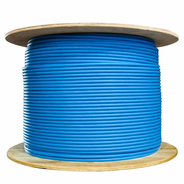
Fiber testing is the process of verifying the performance of optical fiber cabling. This process includes a range of tests and measurements such as insertion loss, optical return loss, and fiber length. It encompass.
[PDF]
Pricing (EUR) Filter the results in the table by unit price based on your quantity. Bus Bar Connectors are available at Mouser Electronics. Mouser offers inventory, pricing, & datasheets for Bus Bar Connectors. Flex-Cable is a leading provider of bus bar solutions for all types of battery connections. We can design and create bus bars using a variety of materials to meet all customer specifications. Let us solve your battery and capacitor conductor routing and space problems! Flex-Cable bus bars provide:. From copper busbar and aluminum busbar options to insulated busbar and busbar trunking systems, our Busbar Products Pricing Guide helps you balance quality, durability, and budget to make the right choice. The European busbar market has witnessed significant growth and transformation over the years, driven by advancements in electrical infrastructure, increasing energy demands, and stringent environmental regulations. At EMDEP we have developed a busbar tester which is a precisely solution to perform High Voltage test for this type of product. A universal concept with interchangeable. Navigating Europe's complex cable manufacturing landscape requires precision. This definitive guide cuts through the concentrated USD 49. 40 billion market (2024 valuation), empowering procurement professionals and infrastructure developers to strategically source. We provide data-driven insights, a.
[PDF]
Small Form-factor Pluggable (SFP) modules are a cornerstone of modern high-speed networks, enabling flexible, hot-swappable fiber connections in dense deployments. This article reviews reliability, testing practices, and real-world considerations from a QA and MTBF perspective. We explore. Add Judgment Criteria of Reliability Test Results, vulcanizing Corrosion requirement and airborne Contaminants Test. Make some editorial modifications. 5 Stress Test Requirements for Optical Module Components. ABSTRACT: The Optical Internetworking Forum (OIF) has been instrumental in standardizing coherent optics at the physical layer, with the 400ZR implementation agreement (IA) being a significant achievement. This white paper reports on the performance evaluation of 400ZR and OpenZR+ pluggable modules. Linear pluggable optics have emerged as a transformative technology in the telecommunications and data center industries, representing a significant evolution from traditional transceiver architectures. This technology enables direct fiber-to-chip connections without the need for intermediate. Long Term Reliability Methodology of Next Gen Pluggable Optical Modules for PAM4 Applications in Hyperscale Datacenters V. The coherent optics landscape has gradually transitioned from engineered links on closed systems to today's multi-vendor, standards-driven ecosystem.
[PDF]