Single mode and multimode fiber optic cables are two different types of fiber optic cable aimed at different use cases. Single mode cables are typically made with a single strand of glass at their core, leading to a n.
[PDF]

This article will give you an overview of the use cases for fiber-optic networking, some of the terms used in fiber networking, and suggestions for setting up a fiber network. Once you understand the basic concepts, you can check out my Recommended Equipment section toward. Fiber tapping is a network tap method that extracts signal from an optical fiber without breaking the connection. Tapping of optical fiber entails diverting some of the signal being transmitted in the core of the fiber into another fiber or a detector. Fiber to the home (FTTH) systems use beam. Optical fiber is a technology used to transmit data by sending short light pulses along a long fiber, which is typically made of glass or plastic. In optical fiber communication, metal wires are preferred for transmission because the signals travel more safely. Optical fibers are also resistant to. Photo: Light pipe: fiber optics means sending light beams down thin strands of plastic or glass by making them bounce repeatedly off the walls. This is a simulated image. Note that in some countries, including the UK, fiber optics is spelled "fibre optics. " If you're looking for information online. This manual covers everything about fiber optic cables, how they work, where they are used, and what is new in this area of technology. The choice of fiber optic cable depends on the specific needs of the application, as well as the.
[PDF]

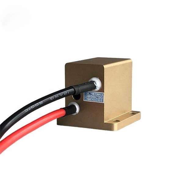
The basic design of an optocoupler consists of a light source, usually an LED (Light-Emitting Diode), driven by the input signal which could be a digital or analogue voltage/current depending upon the characteristics of the light source. An optocoupler (or opto-isolator) is a component that transfer signals between circuits using light. In this guide, you'll learn how they work and how you can use one in your own projects. Optocouplers are very useful when you need to isolate different sections of a circuit, for example in power. Optocouplers, also known as opto-isolators, uses infrared light to transfer electrical signals between two electrically isolated circuits and are commonly classified by their photosensitive output device What is an Optocoupler? An optocoupler (also called an opto-isolator, photo-coupler, or optical. An optocoupler is a tiny part that moves signals between circuits without letting electricity jump across. It uses light to do the job, which helps keep things safe. That way, noisy signals, voltage spikes, or weird grounding issues don't mess with sensitive electronics. Opto-isolators prevent high voltages from affecting the system receiving the signal. We will explore the basics of optocoupler selection and their functionality, helping.
[PDF]

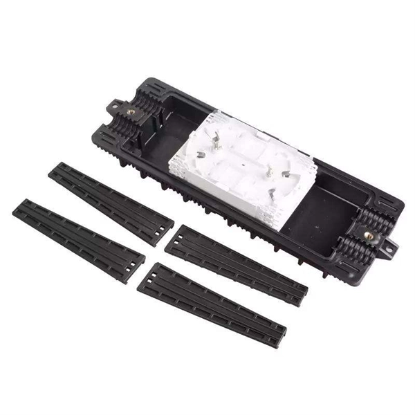
It is a technique that uses controlled heat to permanently fuse two optical fiber ends together. Unlike mechanical splicing, which relies on alignment sleeves and index-matching gel, this thermal approach creates a continuous glass path between fibers. Optical fiber transmission has the advantages of wide transmission frequency, large communication capacity, low loss, no electromagnetic interference, small diameter of optical cable, light weight, rich source of raw materials, etc., so it is becoming a new transmission medium. When light is. Common splicing methods include optical fiber cold splicing and optical cable hot fusion splicing. Advantages and disadvantages of fiber optic cold splicing Fiber cold splicing refers to using special tools to mechanically connect two optical fibers. Its advantages include: Simple operation and. This is part 6 of a tutorial on passive fiber optics from Dr. The tutorial has the following parts: Optical fibers can be joined together, such that light is efficiently transferred from one fiber to another. There are various possibilities: Mechanical splicing means that two fiber ends. This guide reveals the secrets to fusion splicing with little fluff—just proven, straightforward techniques refined from years of work in the field. The result is a joint that closely matches the.
[PDF]
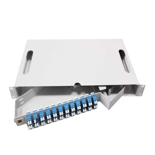
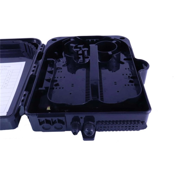
Learn how to install a fiber optic termination box step-by-step for FTTH projects. Covers mounting, splicing, routing, labeling, and testing for indoor/outdoor use. Installing a fiber optic termination box is one of those jobs that looks simple on paper, but it's easy to do. A common question we receive is: How do you use a fiber-optic termination box? We recommend using a termination box if you're ordering an assembly with more than two strands. It helps keep your connectors free from contamination and dust, while also keeping your assembly neat and organized. Check. A Fiber Termination Box, also known as a Fiber Distribution Box, is a crucial component in fiber optic networks. They also feature resistance to moisture, impact, chemical exposure. Whether you're a network technician, IT professional, or simply looking to understand fiber optic networks better, this guide will provide you with the essential knowledge for working with fiber termination box.
[PDF]
This comprehensive guide will delve into the most effective practices, key considerations, and strategic approaches for designing and implementing an efficient cabling system within a data center environment. At the core of data center connectivity are fiber optic cables, which are thin strands of plastic that transmit data using light signals or wavelengths, offering unparalleled speed and efficiency. The data superhighway paved by fiber optics forms the backbone of modern data centers, ensuring rapid. An end-to-end cabling system is an ideal solution for data centers especially when time for traditional cable installation and termination is limited. Explore advanced configurations, testing protocols, and industry best practices. As the demand for data surges, these switches become more vital in sustaining networks that are efficient, scalable, and. As data centers continue to grow in complexity and scale, efficient fiber optic cabling is essential for maintaining high performance, reliability, and scalability. Proper planning and implementation of cabling infrastructure can significantly reduce downtime, improve airflow, and ensure. center hardware layout design. This map should include the cabinet placements, patch panels, hardware, port-counts, trunking locations and power access connection points. Future plans for change will be discussed, as well as the bandwidth required. infrastructure design. The design's intent is to.
[PDF]
It plugs into network equipment (like switches, routers, or servers) and its primary function is to convert electrical signals from the device into light signals for transmission over fiber optic cables, and then convert received light signals back into electrical signals. People can also refer to an optical transceiver as a fibre optic transceiver or optical module. A transceiver is a mix of the words 'transmitter' and 'receiver. ' An optical transceiver includes an optical. This section explains the core IP and optical components used in traditional hierarchical networks. It helps readers understand the router, transponder, ROADM, amplifier, and management elements that form the baseline network architecture. In fiber optics, this data is sent in the form of pulses of light over an optical fiber, at very high speeds and across long distances. Essentially, these devices. Why choose Nokia for your optical network? The Nokia industry-leading optical network portfolio leverages highly vertically integrated coherent optical engines and includes the latest generation of open and flexible optical line systems, intelligent coherent pluggables, ultra power-efficient. This page provides an introduction to optical wireless networks. It compares short-range (directed and diffused) and long-range optical wireless technologies, highlighting their differences. The broadband wireless.
[PDF]
Plan your outdoor fiber installation carefully by surveying the site, choosing the right cable type, and following FOA and OSP standards to ensure reliability. Select the best installation method—direct burial, aerial, conduit, or underwater—based on your environment and. Underground cables are pulled in conduit that is buried underground, usually 1-1. 2 meters (3-4 feet) deep to reduce the likelihood of accidentally being dug up. In extreme cold climates, cables may need to be buried at greater depths where there temperatures are colder and frost penetrates to. We are Jera line, a factory that produces cable infrastructure products. FODB-8 is installed with adapters, splitters, drop cable patchcords, pole bandings, and fiber cable slack storage. Use. pport cables and splice enclosures. Cost of rack Wire Splice B x (200 (50' Mi As ve 1'-0" wide (min) concrete apron. rons shall be sloped away from box. Cost of apron o d oun. FTTP or fiber To The Premises applications have reinforced the importance of reliable and stable fiber optic terminations. Good quality fiber laying and termination systems help achieve minimal back reflection and low signal loss. They also feature resistance to moisture, impact, chemical exposure. Fiber optic cable may be installed indoors or outdoors using several different installation processes. Outdoor cable may be direct buried, pulled or blown into conduit or innerduct, or installed aerially between poles.
[PDF]
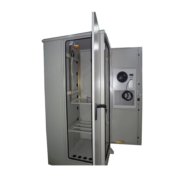
A distribution box is used to receive electrical power from a main supply and distribute it to multiple branch circuits in a safe and controlled way. It helps protect circuits, organize electrical connections, and improve maintenance efficiency. Distribution. Distribution boxes are commonly used in residential and commercial electrical systems. To learn more about distribution boxes and how they work, keep. A distribution box is a vital piece of equipment that ensures the effective and safe distribution of electrical power in various parts within a building or complex. Today, electrical systems are essential for homes and industries. It acts like a hub or traffic controller, managing power flow to different areas or devices. Key components include circuit breakers, fuses, bus bars, and internal wiring for safety and. This ultimate guide explains what a distribution box does, its internal components, common types, real-world applications, and how to select the right DB Box for your project. We also highlight how reliable manufacturers like NUOMAK support stable, compliant, and cost-effective power distribution.
[PDF]

This comprehensive list of top 10 online B2B marketplaces and manufacturers will lead you to find your perfect cable trays based on your business requirements. Let's explore the characteristics of these platforms together. The United States is a diverse landscape of top manufacturers spanning various sectors. These companies lead in innovation, technology, and global competitiveness, employing advanced techniques and contributing significantly to the national economy. They represent excellence in production and. Snake Tray: Snake Tray manufactures innovative cable management and power distribution products all designed to save on installation costs. All of our products have green features and are made in the USA. Established in 1903, nVent ERICO has been an integral rail industry supplier of niche. Other products such as frames, handles, guides, cable rings, shelves, baskets, racks, cable management panels, container holders, shelf dividers & sterilizer carts are available. is estimated to have 10-49 employees. estimated yearly. American Tech Supply a division of American Data provides a complete end cable tray, basket tray and Raceway System solution. Cable Tray and Cable ladder along with wire mesh trays are cable support systems that run large quantities of power or data cable overhead or under floors. com provides buyers with a free hand to explore customized cable.
[PDF]

Shop our range of high-quality fiber optic attenuators for telecom and datacom applications. Use this optical attenuators buying guide to compare major types, define selection criteria, and find suppliers: 🔬 Encyclopedia article: optical attenuators 📦 Top-level product category: optical components and devices Click on a logo to get to the details of that supplier's offer. Our list of. Find reliable variable optical attenuator prices for various models. FS fixed and variable fiber optic attenuators with leading attenuating fibers guarantee consistent and stable fiber attenuation (0~60dB) in WDM transmission. Optical Attenuators Market report is further segmented By Region (North America, Europe, Asia-Pacific, South America, Middle-East and Africa). In 2024, the market for Optical Attenuators Market was valued at USD 1. It is anticipated to grow to USD 2. 5 Billion by 2033, with a CAGR of 9. The types include VOAs made of 2D MEMS having good repeatability and low cost; VOAs made of 1D MEMS having >70 dB high attenuation; VOAs made of fiber directly coupled to fiber MEMS having ultra-low loss <0. We provide support, services, comprehensive training and the resources you need. It's all part of what we do to maximize the value of your VIAVI investment. Contact us for more information or to receive a price quote. We have the experts.
[PDF]
When working with laser light, a plate or cube beamsplitter offers the best combination of optical performance and power handling. a beamsplitter is choosing the right coating. Beamsplitters are optical components used to split incident light at a designated ratio into two separate beams. Additionally, beamsplitters can be used in reverse to combine two different beams into a single one. Beamsplitters are often classified according to their construction: cube or plate. A beamsplitter is an optic that splits light into 2 directions. The split ratio of light transmittance and reflectance is 1:1 and is called a half mirror. Good fit for large beam size applications at a reasonable price. This precise ability to direct light paths makes beam splitters essential in various applications, including imaging systems, laser. Plate beamsplitters are made using a coated substrate, and thus exhibit beam offset and ghost reflections from the second surface. Cube beamsplitters avoid beam displacement by working at 0° angle of incidence and placing the coated surface between two right angle prisms, but power handling can be. This Beamsplitters Selection Guide outlines the core types of beamsplitters, explains how they work, and provides practical advice for choosing the best one for your application. Newport offers a wide variety of Beamsplitters in various shapes.
[PDF]

Mechanical Optical Switches: Switching times typically range from 1-10ms, suitable for long-distance transmission scenarios where latency is not critical (such as backbone network protection switching). Solid-State Optical Switches: Based on thermooptic or electrooptic effects, response. We lead the industry in optical switch technology, delivering the lowest insertion loss (0. 2 dB), fastest switching speed (10 ns), broadest wavelength range (300–2400 nm), widest fiber compatibility, highest optical power handling (50 W), and space-qualified reliability. Backed by over 25 years of. Use this optical switches buying guide to compare major types, define selection criteria, and find suppliers: Professional purchasing of high-value photonics products is a substantial responsibility, where a structured decision-making process is essential. RP Photonics offers a lot of help: Get. This document is a troubleshooting and selection guide for common optical switch failures, compiled based on over 500 field cases. These switches are built on proven, reliable optomechanical technology that has seen more than 30 years of successful operation. Each. The POLATIS ® Series 7000 384x384 all-optical circuit switch is designed to meet the most demanding applications with exceptionally low optical loss, compact size, and fast switching speeds. With support for Software-Defined Networks (SDNs) via embedded NETCONF and RESTCONF control interfaces, the.
[PDF]

