
A typical fiber connector (the plug-and-socket type you'd find on patch panels) adds around 0. 5 dB of loss per connection. Higher-quality connectors under ideal conditions can get down to about 0. Attenuation in fiber optics is the gradual loss of light signal strength as it travels through a fiber cable. It's measured in decibels per kilometer (dB/km), and it determines how far a signal can travel before it becomes too weak to read. A standard single-mode fiber operating at 1550 nm loses. Optical Signal Attenuation is the single greatest factor limiting the distance and performance of your network. Understanding it is crucial for anyone involved in data centers, telecommunications, or enterprise networking. This guide will demystify signal loss, explore its causes, and show you how. F iber optic networks rely on the efficient transmission of light signals to deliver high-speed data over long distances. However, various factors can cause signal degradation, leading to performance issues and reduced network reliability. Fiber optic signal loss, also known as attenuation, occurs. Home1 / Blog2 / fiber optic3 / How to Fix High Attenuation & Signal Loss in Fiber Optic Networks. Signal loss in Fiber Optic networks can make data slow. High attenuation makes your system not work well. You may see slower speeds and less steady connections when signal loss goes up. Things like impurities in the fiber core and reflections at the core-cladding edge cause this drop.
[PDF]
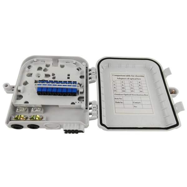
Designed to provide a clean, secure, and accessible termination point for indoor fiber connections, these outlets ensure optimal signal quality and minimal interference in residential and commercial environments. As fiber-to-the-home (FTTH) and fiber broadband continue to replace traditional copper infrastructure, the Fiber Optic Socket Wall Outlet has become an essential component of modern optical networks. These outlets act as the key connection point between your fiber optic cables and the devices that require fast, stable internet. A fiber wall socket (also called an optical termination outlet or FTTH outlet) is the critical endpoint where your home's fiber optic cable connects to the Optical Network Terminal (ONT). It ensures a clean, stable interface between the ISP's fiber network and your router—impacting speed, latency. These outlets, also known as fiber wall sockets or fiber optic outlets, play a crucial role in facilitating the transmission of data over long distances at incredible speeds. Splice holder is included. The optical trunk outlet is designed for installation in Schneider/Thorsman 80mm ducts. Trunk outlet for fiber optics delivered with adapter and pigtails.
[PDF]

The process involves a combination of national infrastructure, local engineering, and property-level setup. In this guide, we'll break down the fiber installation process from start to. This guide walks you through the complete fiber installation process, from checking availability to optimizing your Wi-Fi network performance. Fiber transmits data using light signals through glass strands, delivering faster speeds and lower latency than cable or DSL connections that rely on. In this article we'll break down how fiber internet is installed - from the network fiber drop outside your house to the in-home setup with your router and gateway - and what you should expect at each stage. Fiber optic internet is generally installed in the following 5 steps, which we'll dive. Want lightning-fast internet at home? Fiber optic installation is the way to go! It's super reliable and perfect for streaming, gaming, or using multiple devices. This guide breaks down the process in easy steps so you know what to expect. BCS Consultants, a trusted fiber optic installation company based in California, provides end-to-end fiber optic services, including expert planning. However, setting up a fiber optic connection to your router can seem daunting if you're unfamiliar with the process. In this guide, we'll walk you through how to connect a fiber optic cable to a router safely and efficiently. Why Use Fiber Optic Internet? Before diving into the setup, let's quickly.
[PDF]
The process involves a combination of national infrastructure, local engineering, and property-level setup. In this guide, we'll break down the fiber installation process from start to finish and explain key components such as fiber cabinets, flower pods, ducting, and ONT. Our fiber optic installation process covers everything from planning and preparation to termination and testing. But how does it work? Keep reading to find out. What Is Fiber Optic. This fiber optic installation method statement covers the termination of fiber optic cables with patch panel, network distribution cabinet NDC and door junction box but can be applicable for any kind of network installations. Roles and Responsibilities: The electrical manager shall be responsible. Setting up a fiber optic network requires careful planning and execution. This guide provides a step-by-step overview of the installation process, ensuring a smooth transition from traditional cabling systems. Introduction Installing a fiber optic network can seem daunting, but with the right. This beginner-friendly guide will walk you through the step-by-step process of fiber optic cable installation for each method, highlighting best practices, tools, and considerations. Unlike traditional copper wiring, fiber optics installation provides superior bandwidth, faster speeds, and resistance to electromagnetic interference.
[PDF]
In this video, Joe would display how to connect SC fiber optical connector in 2 minutes. Related product:. Step 4 i s to affix the fiber to the connector. The fiber should be inserted into the connector until it is flush with the ferrule end. Step 5: Let the epoxy cure. These connectors ensure high-quality signal transmission, which is essential for reliable internet and communication services. SC APC connectors offer superior optical. There are many types of fiber optic connectors, including SC, LC, FC, ST, D4, MU, MT/MPO, etc. These connectors can be divided into single-mode and multi-mode fiber optic connectors according to their structure and purpose. To learn more about the types of fiber optic connectors, click here: Types. The global SC fiber optic connector market is valued at approximately 903 million USD in 2025 and is projected to grow steadily, which reflects its continuing role as a standard interface in fiber infrastructure, including plant backbones and industrial automation links, according to SC connector. SC fiber connectors, or Subscriber Connectors, are widely used in telecom and networking for their strong performance and easy handling. They're known for a secure push-pull connection that's quick to insert and remove.
[PDF]
This paper focuses on a bidirectional isolated dual active bridge (DAB) based dc/dc converter as one of the potential modules for photovoltaic system applications. The DAB converter possesses the functions of bidirectional power ow transfer, and has some advantages, including electrical isolation. Among the available technology, the photovoltaic (PV) panels is a popular solution. Thus, targeted Power Conditioning Systems (PCSs) are drawing increased attention in research. Microconverter is one of the PCS that can support versatile applications in various power line architectures. This work. A solar PV system typically has two safety disconnects. The first is the PV disconnect (or Array DC Disconnect). The PV disconnect allows the DC current between the modules (source) to be interrupted before reaching the inverter. The AC Disconnect is used.
[PDF]
Testing solar panels is easy with a multimeter! To test the current, simply connect the multimeter to the panel's output. Set it to read DC current. To test voltage, set your multimeter to. A $15 multimeter and 5 minutes of testing can diagnose most solar panel problems. Measure Voc (open circuit voltage) — if it reads 0V, the panel or wiring is dead. If it reads 60–80 % of rated, a bypass diode has failed. If Voc is normal but the system is not producing, the problem is downstream. Solar panels are usually tested under standard conditions using a light source that mimics the light from the sun on a clear day. You can use the following method if you want to test your solar panel under standard conditions. We will cover the. A multimeter is a tool that measures the voltage, current, and resistance of an electrical circuit. Fluke recommends using the Fluke 117 Electrician's Multimeter or Fluke 283 FC CAT III 1500 V Digital Multimeter to test solar modules. This helps you spot issues early and keep your system running efficiently. By the end of this guide, you will be equipped with the knowledge to diagnose.
[PDF]

A 630A MCCB means the breaker is rated to handle up to 630 amperes of continuous current without tripping under normal conditions. This type of MCCB is commonly used in industrial power distribution panels, commercial buildings, and large electrical systems where higher current. A Molded Case Circuit Breaker (MCCB) is a protective device designed to automatically disconnect electrical circuits during overloads or short circuits. This type of. This ComPacT NSX630N is a complete 3P 3d fixed circuit breaker designed to optimize space and breaking capacity. It is an optimal choice for all standard and specific applications. The breaking capacity (Icu) is 50kA rms at 415VAC 50/60Hz. This product. Fuji Molded Case Circuit Breakers are more compact (especially 100A, 125A, 250A frames) than any breakers on the market, so they take up less space in control panels. U denotes non-interchangeable trip unit. With a 630A frame rating and adjustable settings from 400A to 630A, it offers flexible protection for high-power applications. Ir = 300 - 630A; Icu = Ics = 65kA at AC 440V How to request a quotation How can I request a quotation for more than one product? (Watchlist). GENLITEC POWER® GTS630 630A Automatic Transfer Switch (ATS) Panel is designed for seamless and automatic power switching between the main utility supply and backup generators. Engineered for high-power applications, this ATS ensures uninterrupted power supply, reducing downtime and enhancing.
[PDF]

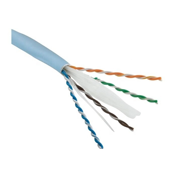
This article provides a detailed technical comparison between fiber optic and copper cables, offering a clear perspective for engineers, network architects, and procurement managers. The core distinction between the two technologies lies in the physics of data. However, the exponential growth in data demand has positioned fiber optic technology as the superior alternative for performance, scalability, and future-readiness., 10G/25G/40G/100G and beyond depending on optics and reach). Copper Ethernet scales too, but practical limits are lower and depend. The two main options are fiber optic cables and copper cables, each with its own advantages and drawbacks. Fiber optic cables are praised for their high performance and scalability, while copper cables remain a cost-effective choice, especially for budget-conscious projects and older systems. Copper wire is more susceptible to interference and has limited data capacity, making optical fiber the preferred choice for modern high-speed. Optical connectivity, utilizing fiber-optic technology, has emerged as the superior choice for modern networking, offering unparalleled performance, reliability, and scalability. For example, a typical 10 Gbps copper Ethernet link (such as Cat 6A) over 100 meters can consume approximately 5 to 8+.
[PDF]

In this video, we will show you Installation example of AC distribution boxMCB type: GYM9Relay type: GSP8-02ATS type: G2RRCBO type: GYR9NMAll products fr. The Project Development Objectives are to improve (i) the reliability and efficiency of electricity supply in Bamako and (ii) the technical and commercial performance of EDM. Does this restructuring trigger the need for any policy waiver(s)? The financing for the Mali Electricity Sector Improvement. Learn how to install a distribution box safely and correctly. Covers wiring, placement, standards, and expert tips for a compliant setup. A distribution box is the heart of any electrical system. It takes the incoming power and safely distributes it to different circuits throughout your building. Whether you are an electrical contractor or a construction brigade, knowing how to properly and safely install distribution boxes is the basis of ensuring the safe operation of the entire system. This article details the process of installing them, which helps you comprehend distribution boxes. The Progressive Dynamics PD4575V Inteli-Power 4500-Series AC/DC Distribution Panel is an advanced all-in-one power management solution designed for recreational vehicles and similar applications. This 75 Amp unit integrates an AC/DC distribution panel with a sophisticated power converter featuring.
[PDF]

Huawei's fiber to the room (FTTR) solution extends fibers to rooms and provides various gigabit Wi-Fi 6 master/slave FTTR units, all-optical components, and optical cable routing tools. This enables home users to enjoy stable gigabit Wi-Fi experience from anywhere in the home. FTTR is generally an extended FTTH (Fiber To The Home) solution. Drop optical cable terminates at ATB (Access Terminal Box). A patch cord of 1 or 2 m. Huawei will soon be selling its "FTTR" system for do-it-yourself fiber optic home cabling in Germany. Huawei FTTR: Bonding tool for fiber optic installation. A special glue. Fibeye provides FTTR(Fiber to the room) solutions, We specialize in Huawei-adapted FTTR solutions that can help you tap into new markets and grow your business. What is FTTR FTTR(Fiber-to-the-room), is an innovative solution that allows telecom operators to bring optical fibers directly into. Guess what, I spotted Huawei's transparent fibre optic offering! The best Wi-Fi is wired Last year, I wrote about Singtel's FibreEverywhere offering, which allows homeowners to install high-speed wired cabling in every room - without any drilling or trunking. Poor Wi-Fi coverage at home is a common. Watch the video to discover how to use the Huawei FTTR fiber installation kit to route transparent optical cables.
[PDF]
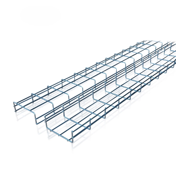
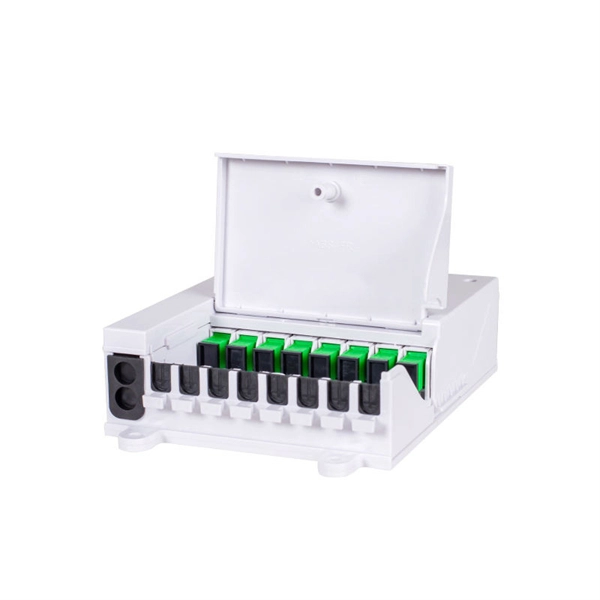
A fiber patch panel is a mounted enclosure—either rack-mounted or wall-mounted—used to terminate, manage, and interconnect multiple fiber optic cables. It acts as a hub for organizing splices and patch cords, streamlining fiber management and preserving signal integrity. Propel Series Sliding Fiber Optic Panels for holding Propel modules, adapter packs and splice cassettes EPX Fiber Optic Panel available in either G2 or LGX/PNL 1U, 2U or 4U fixed or sliding configurations FMT (Fiber Management Tray) Series Fiber Optic Panels FOMS-FPS and FOMS-FPS-HD Fiber. Consolidate your fiber optic connections in industrial environments with our DIN rail patch panel, with a modular design and tool-free installation save space and simplify deployment. Consolidate your fiber optic connections in industrial environments with our DIN rail patch panel, with a modular. Belden offers several Fiber Patching Systems. Cable Organization:. FS offers FHD® FAPs and FHU™ 1U fiber patch panel with LC, SC, MTP®/MPO connectors in singlemode/multimode fiber to deploy medium for high-density fiber optic network applications. Foss FP-series front patch panels are made with the highest accuracy for precise fitting. All panels are tested according to both our own quality measures and international standards before they are sent to customers. In an FTTH network hub—whether a central office, local exchange, or data.
[PDF]
Practice good wiring: secure grounding, neat cable management, proper insulation, and correct wire gauge and breaker size. Include protection devices like breakers, fuses, and surge protectors—each circuit should have its own protection. Comply with standards: Follow NEC, IEC . An electrical panel box, also known as a breaker box or a distribution board, is a crucial component of any electrical system. It serves as a central hub for distributing electricity throughout a building, ensuring that power is delivered safely and efficiently to all the required locations. In this video, we'll walk you through the process of wiring a home distribution box with a detailed connection diagram. Whether you're an electrician or a DIY enthusiast, this guide will help you understand the basics of home electrical distribution. more Welcome to our channel! In this video. Choose the right box based on environment (indoor/outdoor), load capacity, and durability. Check for proper IP/NEMA ratings and material quality. Ensure safe placement: install in dry, accessible areas with good ventilation and at appropriate height (typically ~1. It involves connecting wires and components properly, to ensure safety and efficiency. Good wiring is vital to prevent electrical hazards and keep appliances, lights, and other electrical devices functioning well. It receives power from the main electrical supply and divides it into separate circuits, each.
[PDF]
