from outside the US. EMEA Specific: +49 (0) 228 7489 201 HCS and GiHCS are registered tradema time without notice. This document is for informational purposes only and is not intended to modify or supplement any OFS warranties or specifications relating to any of its. from outside the US. STFOC uses our patented cable jacket construction designed to protect the fiber in the harsh subsea environment. Non-KinkTMSTFOC has a patented design to protect. CommScope bundles hybrid cabling to your custom specifications, using our high-performance fiber-optic, unshielded twisted pair and coaxial cables. Devices deployed at the network edge—a 5G radio, a security camera, or an industrial sensor—require high-speed data connectivity and power. It is technically possible to have a separate fiber and electrical cable, but it adds complexity, cost, and maintenance overhead. Optical hybrid cables address. challenge—OCC has what you need. Our team will make sure the configuration is tailored to your needs and will provide a detailed quote. Email us using the Request a Quote below, or give our team a call. Drive, Avon, CT 0600 erat ing Bend Radiu erat ing Bend Radius Cons from outside the US. Teledyne ODI ofers a comprehensive line of fiber optic and electro/optic hybrid wet mate interconnect products. Wet mate connectors are available in ROV Mate, Stab Mate and Manual Mate configurati sm.
[PDF]

Mechanical Optical Switches: Switching times typically range from 1-10ms, suitable for long-distance transmission scenarios where latency is not critical (such as backbone network protection switching). Solid-State Optical Switches: Based on thermooptic or electrooptic effects, response. We lead the industry in optical switch technology, delivering the lowest insertion loss (0. 2 dB), fastest switching speed (10 ns), broadest wavelength range (300–2400 nm), widest fiber compatibility, highest optical power handling (50 W), and space-qualified reliability. Backed by over 25 years of. Use this optical switches buying guide to compare major types, define selection criteria, and find suppliers: Professional purchasing of high-value photonics products is a substantial responsibility, where a structured decision-making process is essential. RP Photonics offers a lot of help: Get. This document is a troubleshooting and selection guide for common optical switch failures, compiled based on over 500 field cases. These switches are built on proven, reliable optomechanical technology that has seen more than 30 years of successful operation. Each. The POLATIS ® Series 7000 384x384 all-optical circuit switch is designed to meet the most demanding applications with exceptionally low optical loss, compact size, and fast switching speeds. With support for Software-Defined Networks (SDNs) via embedded NETCONF and RESTCONF control interfaces, the.
[PDF]

Precision begins with a quality optical encoder disc in the automation, robotics, and motion control systems of today. This tiny yet essential device transforms physical movement into exact digital signals that dictate speed, position, and direction. What constitutes an optical transceiver? An optical transceiver, a crucial device utilized in optical communication, is an optoelectronic element, allowing the interconversion of optical and electrical signals during the information transmission. It generally has the components for transmission. Therefore, NASA is developing optical communications to address limitations of radio frequency (RF) communications, including: bandwidth, spectrum and overall size of frequency packages and power used. Optical spectrum uses light as a means of transmitting information via lasers. Optical. Optical transceivers are devices that convert electrical signals into optical signals and vice versa, playing a key role in supporting modern high-speed communication networks. They are widely used in data centers and communication systems to enable high-speed, efficient transmission of large. Optical transceiver modules are designed and built by a variety of manufacturers. In the design of optical transceivers, the selection of channel configuration and modulation.
[PDF]
Coherent optical module refers to a typically hot-pluggable coherent optical transceiver that uses coherent modulation (//) rather than amplitude modulation (RZ//) and is typically used in high-bandwidth data communications applications. typically have an electrical interface on the side that connects to the inside of the system and an optical interface on the side that connects to the outside world through a fiber optic cable. The technical details of coherent op.
[PDF]

Bury cables from 12-36 inches (or 30-90 cm) deep. Where plant life, sidewalks, and other utilities already disrupt earth, it's safer to bury at as little as 24 inches or 60 cm, using protective conduits to limit the likelihood of damaged cables by inexperienced maintenance or. Bury cables from 12-36 inches (or 30-90 cm) deep. These facilities are collectively known as communication infrastructure. Knowing the exact depth of these lines is paramount for anyone planning. The short answer, based on general industry standards and the National Electrical Code (NEC), is that fiber optic cable is typically buried between 24 inches (60 cm) and 30 inches (76 cm) deep. However, simply hitting this depth isn't enough to guarantee your network survives. This. The depth at which cable lines must be buried is governed by a combination of local, state, and national regulations, designed to ensure safety, prevent damage, and maintain infrastructure integrity. These laws typically specify minimum burial depths based on the type of cable (e. 5 meters, balancing protection with installation cost and accessibility. With fiber deployments accelerating in urban and rural areas, understanding these depths is essential for efficient planning and maintenance. In high-load areas such as roads or backbone routes, burial depth can reach 48 inches (120 cm) or more. For broader context on underground.
[PDF]
This section provides a list of the top 10 Optical Attenuator manufacturers, Website links, company profile, locations is provided for each company. Viavi Solutions, Inc. DiCon Fiberoptics, 3. What Is an Optical Attenuator? What Is an Optical Attenuator?. According to our (Global Info Research) latest study, the global Optical Attenuators market size was valued at US$ million in 2024 and is forecast to a readjusted size of USD million by 2031 with a CAGR of %during review period. In this report, we will assess the current U. North American market for Optical Attenuators was valued at $ million in 2024 and will reach $. Optical attenuators are devices designed to reduce the optical power of a light beam or signal by a specific ratio (attenuation factor), typically expressed in decibels (dB). Unlike simple beam blockers or shutters, attenuators are intended to maintain the temporal waveform and usually the mode. The VOA series is a highly compact and cost-effective variable optical attenuator designed for efficiently testing and characterizing optical communication systems and optical components, featuring low insertion loss, fast attenuation speed, and built-in output monitoring.
[PDF]
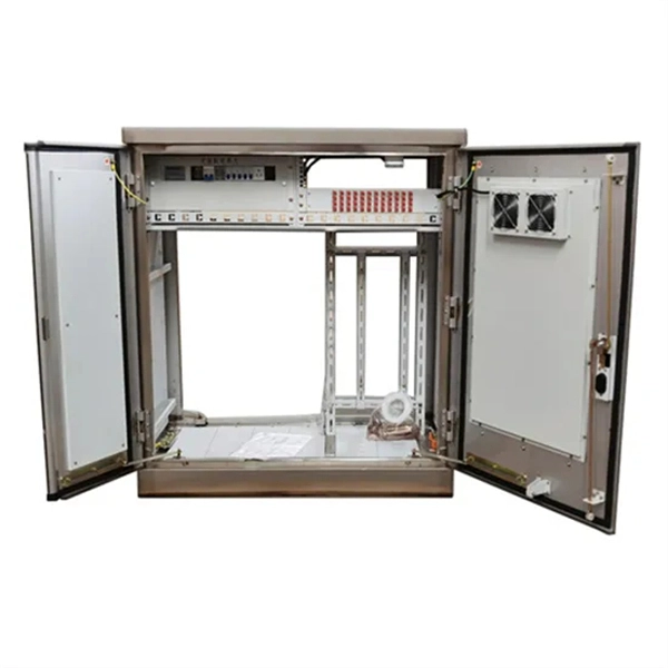
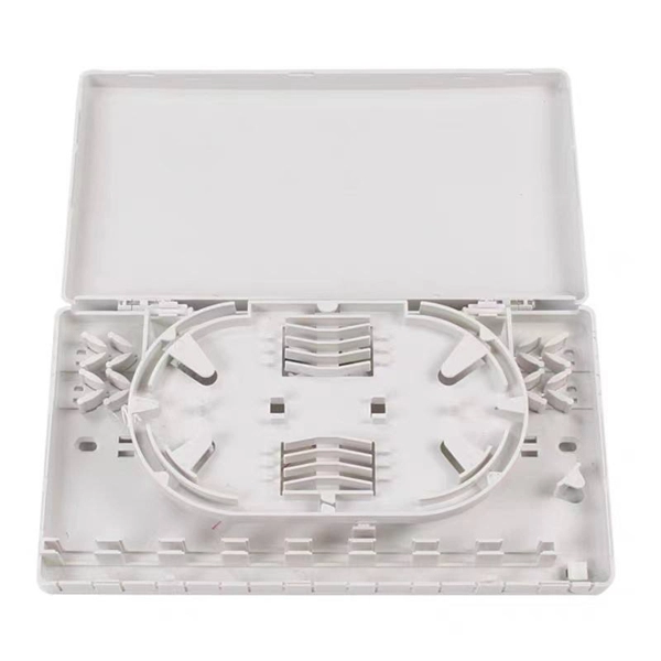
A distribution box, also known as a fiber distribution hub or optical distribution box, is a larger enclosure designed to manage and distribute fiber optic cables to multiple endpoints. It serves as a central point for connecting and organizing numerous fiber optic. Although all three are related to fiber connection and management, their installation locations, functional roles, and positions within the network architecture are fundamentally different. Confusing these devices may lead to non-standard cabling at best, and serious challenges in network. In modern FTTH (Fiber to the Home) and optical communication networks, three types of fiber distribution products are widely used: Splitter Distribution Box, ODF (Optical Distribution Frame), and Fiber Terminal Box. The functions of the four connectors can be. First, let us learn the common point among ODF, fibre optic termination box and fiber optical distribution box, actually, they have similar function, we sort out them as following 4 aspects: 1. fiber termination and optical signal splitting 4. What is the difference between these fiber boxes.
[PDF]
GPON uses passive optical network (PON) is a access in which a single optical fiber from a central location is shared by multiple end users through one or more in series (cascaded). Unlike traditional fiber connections, PON systems distribute optical signals from an (OLT) to many (ONUs) or (ONTs) without requiring active electronic equipment in the distribution network. The absenc.
[PDF]
The SFP-1040-WB is a BiDirectional single fiber strand 10G SFP+ optical module using Tx:1330nm and Rx:1270nm wavelengths. The transceiver supports all 10G rated speeds for Ethernet, SONET, SDH or Fibre Channel networks. SFP-1040-WB must be paired with the SFP-1040-WA model to have an operational. The SFP-1040-Wx series single mode transceiver is small form factor pluggable module for duplex optical data communications such as 10GBASE-ER/EW defined by IEEE 802. It has the SFP+ 20-pin connector to allow hot plug capability. All modules satisfy class I laser safety requirements. Digital diagnostics functions are available via a 2-wire serial. The SFP-1040-Dxx is a DWDM 10G SFP+ optical module. It is available for all 45 DWDM 100GHz ITU grid wavelength channels. The transmitter section uses a 1550nm EML, which is class 1 laser compli Rate Select 0, optionally controls SFP+ module recei e Select 1, optionally controls SFP+ module.
[PDF]
1x9 transceivers are the earliest and oldest-style optical modules. Initially created in the 1990s, they aimed at 100M/1G Ethernet, Fibre Channel, ATM, FDDI, SDH/SONET, and video applications. Then, they were gradually replaced by more advanced and intelligent GBICs, SFPs . Next, we will introduce the three main features of the optical module: The package form is the most important feature of the optical module. The earliest package form was 1*9, and then GBIC, SFF, SFP, Xenpak, X2, XFP, etc. came one after another. Due to the limitations of the era, the 10G optical. An optical module is a typically hot-pluggable optical transceiver used in high-bandwidth data communications applications. The unsung heroes behind this "data voyage" are optical modules—the "optical communication translators" that precisely convert electrical and optical signals. From. Before the 1990s, there was no concept of the optical transceiver industry, and equipment manufacturers independently designed and developed optical transceivers with no uniform standards for size and mechanical interfaces, resulting in poor compatibility and connectivity issues for telecom.
[PDF]
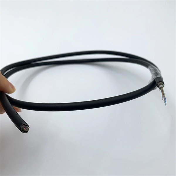
The fiber cores of GYTC8S53 fiber cable is from 2 cores to 288 cores GYTC8S53 is a self-supporting fiber optical cable for outdoor use. Commonly referred to as figure 8 cable, figure 8 fiber cable, figure 8 aerial cable, self-supporting figure 8 cable, or simply figure 8 optical cable, this ingenious structure combines optical fibers with an integrated messenger wire in a distinctive “8” cross-section. This self-supporting design. Hunan GL Technology Co., Ltd Supply 2-144 Cores GYFTC8S Aerial Stranded Figure 8 Fiber Optic Cable With Factory Price, Support OEM, All the figure 8 cables supplied from GL FIBER are complied with IEC 60794-4、 IEC 60793、TIA/EIA 598 A standards. In the GYFTC8S cable, single-mode/multimode fibers are. GYTC8Y is a typical self supporting outdoor fiber optic cable with features of moisture resistance and crush resistance suitable for aerial application. The stranded wires as the supporting part are completed with a polyethylene (PE) sheath to be figure 8 structure. After being coated with steel tape longitudinally, a layer of PE inner sheath is extruded, and then a single layer or double layer thin round steel tape armor is longitudinally wrapped After installation, the. l fibers in loose tubes filled with interstitial gel. Aluminum moisture barr er tape or steel tape armoring options are availa le. A steel messenger wire provides tensile strength. It can work at the temperature from -10 to +70℃.
[PDF]
Find Ecuadorian optical fiber cable joint closure importers on ExportHub. Our team of fiber optic specialists is always available to provide expert advice and tailored solutions, ensuring you get the best connectivity for your needs. LatamFiberHome designs and produces a wide range of optical cables for indoor, outdoor and all kinds of cable structures under customer requirements. At the same time it has a complete set of test equipment to ensure that the cable produced meets international standards and customer requirements. According to the structure can be classified into the dome (vertical) and horizontal (half) two kinds of cable splice closure. Nortra Cables offers custom cable and wire harness design assistance, prototyping and manufacturing services for medical, computer, communications, industrial, and electromechanical applications. Some types of manufactured assemblies include: Loom Harnesses, Box Builds, Prototyping, Coaxial Cable. OPTICALFIBRE CABLES OF EXTENSION CORDS IN 30 PALLETS NET WEIGHT 14843, 50 KG/ 32723, 68 LBS GROSS WEIGHT 15318, 50 KG/ 33770, 85 LBS. The companies listed above have not approved or sponsored Panjiva's provision of any of the information in these.
[PDF]

Lasers, modulators, and photodiodes form the core architecture of optical transceivers, enabling light-speed communication across global networks. Lasers generate the optical carrier. Modulators encode digital information. The choice of laser directly influences a transceiver's distance, data rate, and reliability. What Is an Optical Modulator? A modulator encodes electrical signals onto the laser's light, controlling properties such as intensity, phase, or polarization to represent digital data. It acts as the. Optical modules are compact devices that convert electrical signals into optical signals and vice versa. These modules typically consist of a laser or LED transmitter, a. In the digital age, optical communication technology is evolving at an astonishing speed, and coherent optical modules, as its core components, are leading the transformation from 5G to AI data centers. In 2025, with the explosive growth of global data traffic, the market size of coherent optical. The optical module serves as a crucial component in optical fiber communication systems, operating at the physical layer, which is the lowest layer in the OSI model. Operating at the physical layer of the OSI model, optical modules are core devices in optical. That is, metal medium communication represented by coaxial cables and network cables is gradually being replaced by optical fiber media. Composition of Optical Modules The optical module, known as Optical Transceiver in.
[PDF]


