Designed by engineering firm PJ Ford Engineers, 25 Oldcastle Infrastructure CELL BLOCKS were manufactured to create the 35-foot by 35-foot foundation for the major telecom carrier's wireless cell tower, mi.
[PDF]
Comprehensive Guide to Civil Construction for Telecom Tower Sites In the ever-evolving landscape of telecommunications, the construction of tower sites serves as the backbone for reliable network connectivity. A communication tower foundation design is the structural blueprint that determines the anchor point of the tower on the ground. This article delves into the intricate process of civil construction tailored. Telecom (Telecommunications) towers are a generic description of radio masts and towers built primarily to hold telecommunications antennas. As such antennas often have a large area and must be precisely pointed out, such towers have to be designed and built to limit wind induced movement. So very. With excellent resistance to axial and lateral loads in both compression and tension, they're an efficient and durable foundation that's easy to remove and remediate. Monopole towers are popular in urban areas owing to their minimal footprint and adherence to city planning. The foundation type can be either mat foundation or monopile foundation. If you're planning a new installation, knowing the basics of these foundations can help you establish a secure and durable tower that will be a community asset for years to come.
[PDF]
CT-S3T-2 tower section weight does not exceed 26 kg. Transmission tower weight per meter varies dramatically by voltage level: 35kV towers average 100-180 kg/m, 66kV systems run 150-250 kg/m, 110kV towers range 200-450 kg/m, 220kV structures reach 350-600 kg/m, and 500kV ultra-high voltage towers require 500-800 kg/m. This weight increases. Due to the complicated nature of tower infrastructure, it can prove invaluable to have an engineer approved recommendation for solutions that will accommodate your particular project. We offer a Tower Recommendation Proposal Consultation Service, providing a detailed report that you can use for the. 18m Telecom Tower Ma /www. inf. ASMTower automatically performs load calculation on telecom structures, wind load, ice load and dead load according to the following design standards: ASMTower performs wind and ice load calculations according to the chosen code and distributes the resulting loads, along with the weight of the. Get Latest Price from the seller Khan Enterprises - Offering Selp Sport Wi-Fi Tower, Size: 18 Mtr Rtt at ₹ 3500/meter in Bengaluru, Karnataka. Get WiFi Tower at lowest price | ID: 20500615430. Now, let's take a look at the pricing options: 1. Non-upgradeable: • 12 meters: R49,990. 00 ex VAT ex works PLUS R49,000. 00 ex VAT for site visit, civils, and installation.
[PDF]

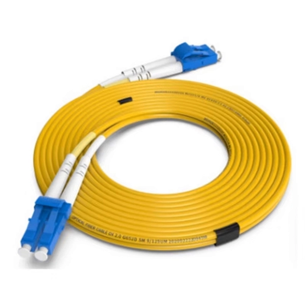
Buyers typically pay a range for fiber optic cable per foot depending on fiber type, jacket, and shielding, plus installation considerations. This guide outlines typical cost ranges and the main drivers behind pricing to help formulate a budget and estimate expenses. The Fiber Broadband Association has partnered with Cartesian to research the cost of deploying fiber and provide insight on how these costs are evolving over time. In preparing this second edition of the Fiber Deployment Cost report, Cartesian gathered inputs from a wide variety of firms building. With 19+ years of experience installing fiber-optic cables at over 20,000 locations, we've seen how prices vary based on cable type, project scope, and installation complexity. This information can help project leaders engage with providers and network operators in their area. This data is based on cost information. As of August 2025, with global internet penetration reaching 67. 56 billion users worldwide, the demand for faster, more stable connections is at an all-time high. Fiber-optic technology, which transmits data via light through glass or plastic strands, offers unparalleled performance. Annual study tracks drivers to fiber broadband deployment cost WASHINGTON, D. — (January 22, 2024)—The Fiber Broadband Association today announced the results of its 2023 Fiber Deployment Cost Study, conducted by Cartesian, which provides the industry's benchmark to help fiber broadband service.
[PDF]
An optical module is a typically hot-pluggable optical transceiver used in high-bandwidth data communications applications. Optical modules typically have an electrical interface on the side that connects to the inside of the system and an optical interface on the side that connects to the outside world through a fiber optic cable. The form factor and electrical interface are often specified by an int. Electrical Interface TypesThere have been multiple variants of the electrical interface of optical modules that have been used over the years. The earliest forms of optical modules had an analog electrical interface. In the transmit dir. Many different forms of optical modulation and multiplexing have been employed in optical modules. The most common modulation technique historically has been or NRZ.
[PDF]

Urban Areas: 25–40m spacing (concrete poles, 10–12m height)., steel lattice structures). Factors: Cable weight (kg/km) Ice loading (up to 50mm. The Fiber Optic Association, Inc. (FOA) was founded in 1995 to help develop the workforce to build the fiber optic networks to support a rapid expansion in communications and the Internet. The charter of the FOA was to promote professionalism in fiber optics through education, certification, and. to n utral comm. cable R. FO-CS JOINT USE CLIMBING SPACE REQUIREMENTS 51. APPENDIX A - COVER SHEET / TOC 52. RUS DRAWING #PM12 58. CHECK. d suppliers of electrical construction services. They define a minimum baseline of quality and workmanshi for installing electrical products and systems. NEIS® are intended to be referenced in contrac documents for electrical construction ation or liability to users of this publication. Choose the type of pole The basic pole height is 7m and the tip diameter is 150mm. In case of special sections, crossing obstacles or roads or railways, the pole height of 8m, 9m, etc. can be selected. Cables 300 V or less need to be a minimum two feet over the street light. Climbing Space is an unobstructed, vertical space along the side or corner of the pole. In gen-eral, it consists of an imaginary box, 30-inches square, extending at least 40 inches above the highest communications cable or.
[PDF]
Compared to conventional metallic cables, optical fiber provides an advantage of low loss (~ 0. 2dB/km) and wide bandwidth (several hundred MHz to THz) to enable long-distance, high-capacity communication. Fiber-optic communication is a form of optical communication for transmitting information from one place to another by sending pulses of infrared or visible light through an optical fiber. The light is a form of carrier wave that is modulated to carry information. Fiber is preferred. It was almost a century later before optical-based communication was put to practical use, thanks in large part to the invention of optical fiber and lasers. A laser's stable, highly directional beam of light (emitted from tiny semiconductor windows that measure just a few hundred thousandths of a. In 2020, we celebrated the 50th anniversary of the invention of low-loss optical fiber — an innovation that has transformed the way we connect and that lies at the cornerstone of our communications revolution. In a Corning lab on a Friday afternoon five decades ago, a single strand of glass and a. Fibre optics and optical communications is the use of thin strands of glass for sending information encoded into light over long distances. Total internal reflection prevents light inserted into one end of the fibre from escaping through the sides. Transferring information optically in this way.
[PDF]

In this guide, we break down the two core stages of optical fiber manufacturing: preform production (shaping the precursor material) and fiber drawing (transforming the preform into thin, usable fiber). Optical fiber preforms are the starting point behind every kilometer of fiber optic cable. Though rarely seen by end users, these cylindrical glass rods serve as the base material from which high-speed optical fibers are drawn. As global communication relies more than ever on fiber networks—from. 📦 For purchasing, use the RP Photonics Buyer's Guide for fiber preforms. It provides an expert-curated supplier directory, buyer-focused technical background information, and structured selection criteria to support professional procurement decisions. During the fiber drawing process, the preform is heated and drawn into a. The production of optical fiber is a precision-driven process that transforms raw materials like silicon tetrachloride into ultra-thin, high-performance fibers capable of transmitting terabits of data over thousands of kilometers. Who invented optical fiber and when? Corning scientists Dr. Peter Schultz, and Dr.
[PDF]

The document discusses optical detectors used in fiber optic communications systems. It describes the functioning of PIN photodetectors and avalanche photodetectors (APDs). Their performance. An optital detector is a device that converts light signals into electrical signals, which can then be amplified and processed. Such detectors are one of the most important components of an optical fiber communcation system and dictate the performance of a fiber optic communication link. PIN Photodiode A PIN photodiode is a widely. Detectors perform the opposite function of light emitters. The most common detector is the semiconductor photodiode, which produces current in response to. It explains how these devices use optical fibers to measure quantities like temperature, mechanical strain, pressure, and vibrations by detecting changes in light propagating through the fiber. A central focus is on sensors based on fiber Bragg gratings, where the Bragg wavelength is sensitive to. Optical Power Meters: These devices measure the power of optical signals in fiber optic cables. This information helps in maintaining signal integrity and quality across the.
[PDF]
com is a free cell tower locator that maps over 2. Use the interactive map above to find cell towers near you — including 5G, 4G LTE, and legacy towers — with precise GPS coordinates sourced from the FCC database. Search and locate over 2. 8 million cell tower locations, cell phone towers, and 5G towers across the United States. Search, analyze, and export detailed information about mobile network infrastructure, cell phone towers, and telecommunications sites using official FCC data. What is. WARNING: Setting the type to DAS will cause the tower to split into individual cells. Explore network coverage by operator and country, and more! What is OpenCelliD? OpenCelliD is working towards creating an open cellular dataset that is driven and inspired by the community. This cellular data is used for a multitude of commercial/private purposes by patrons worldwide. Fix dead zones, compare carriers, and get the signal you need. Everything you need to find, navigate to, and understand cell towers. See every cell tower around you plotted on an.
[PDF]

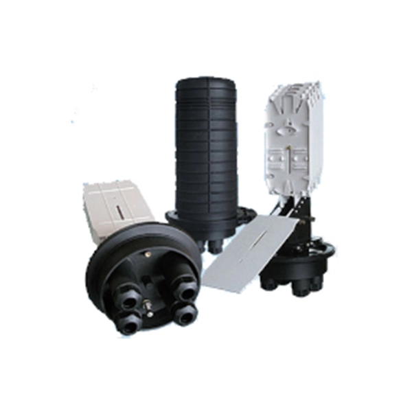
Because fiber optic cables don't come in one continuous length, sections must be joined together through splicing. This process fuses two glass strands so light signals can travel through them without interruption. Below is a detailed look at each step of fiber optic network construction, including key terms and methods used across the industry. Engineers and. We are experts in the installation and use of fiber optic cable to residences, apartment buildings, businesses and cell sites. We complete complex construction projects consisting of aerial and underground deployments in varied, often difficult, working environments. Our services include everything. The Fiber Optic Association, Inc. (FOA) was founded in 1995 to help develop the workforce to build the fiber optic networks to support a rapid expansion in communications and the Internet. Delivers state-of-the-art fiber optics solutions by developing high-tech equipment and subcontractor expertise. Utilizes state-of-the-art technologies to splice a wide variety of different. This recommended practices document is a comprehensive manual for optical fiber construction and testing. Sections are included for project management; cable handling, testing and equipment; overhead cable placement; underground cable placement; underground enclosures; bonding and grounding; cable. 4. FO-VC2 JOINT USE - VERICAL MIDSPAN CLEARANCES 48. FO-GB GROUNDING AND BONDING 49.
[PDF]

This article will guide you through the process of troubleshooting fiber optic connections, with a focus on ensuring proper TX and RX alignment and how to correctly switch patch cables to resolve issues. Proper connection of fiber optic cables is essential to harness these benefits fully, as even minor errors can lead to significant performance issues like signal loss. When issues like signal loss, slow speeds, or intermittent connectivity arise, systematic troubleshooting is key. This guide will walk you through diagnosing and resolving common. The process to connect fiber optic cable to router requires careful attention to detail, but I'll walk you through every critical step with the precision and clarity you deserve. This comprehensive guide combines industry standards with field-tested practices to ensure you achieve a rock-solid. Fiber optic cables are widely used in modern networks for their high-speed data transmission capabilities and resistance to electromagnetic interference. However, like any other networking technology, fiber optics can encounter issues that disrupt communication. One of the most common problems in. Fiber optic internet delivers blazing-fast speeds and reliable connectivity, making it a top choice for modern homes and businesses. Their ability to transfer large amounts of data at lightning speed makes them a go-to for efficient communication. Knowing how to avoid signal loss in.
[PDF]

This Code consists of the introduction, definitions, grounding rules, lists of referenced and bibliographic documents, and Parts 1, 2, 3, and 4 of the 2023 Edition of the National Electrical Safety Code. The Institute of Electrical and Electronics Engineers, Inc. 3 Park Avenue, New York, NY. Climbing Space is an unobstructed, vertical space along the side or corner of the pole. In gen-eral, it consists of an imaginary box, 30-inches square, extending at least 40 inches above the highest communications cable or other facility and 40 inches below the lowest communications cable or other. The Fiber Optic Association, Inc. (FOA) was founded in 1995 to help develop the workforce to build the fiber optic networks to support a rapid expansion in communications and the Internet. The charter of the FOA was to promote professionalism in fiber optics through education, certification, and. There are a number of ways of finding out more about cabling standards. You can buy a complete copy of the EIA/TIA or ISO/IEC standards which can be very expensive and wade through page after page of standards language. You can also get catalogs and/or visit the websites of a number of cabling. to n utral comm.
[PDF]

