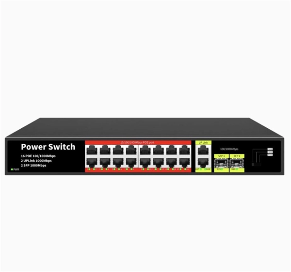
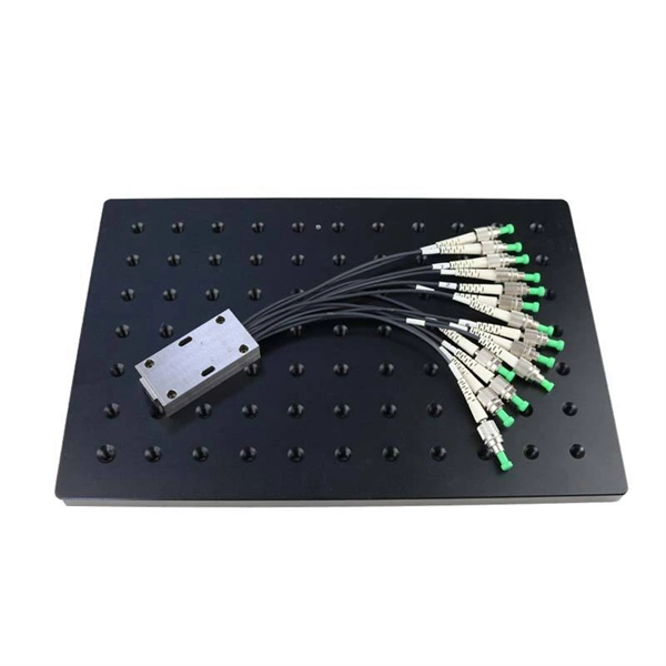
As an essential component of optical fiber communication, optical modules are optoelectronic devices that facilitate the conversion between optical and electrical signals during the transmission process. Operating at the physical layer of the OSI model, optical modules are core devices in optical. An SFP (Small Form-factor Pluggable) is a compact, hot-pluggable transceiver module that allows networking equipment — including switches, routers, servers, and media converters — to support different physical media, such as optical fiber or copper, without replacing the host hardware. This modular. Analog Devices' optical networking solutions address a wide range of applications in data center, enterprise, and telecom markets. They enable power efficient and small form factor optical modules to support network traffic and bandwidth growth driven by the digital economy, social media, streaming. Everything you need to build an optical network from end-to-end. Thin-film filter and PLC based AWG for multiplexing, a full suite of components for optical amplification use, optomechanical or MEMS-based switches for protection or surveillance application, Tap PD for power monitoring and VOA for.
[PDF]
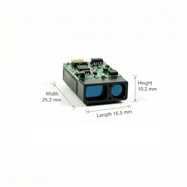
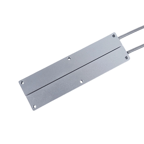
In this guide, we'll break down the essentials, explore different wiring configurations, and provide you with practical tips to get your sensors up and running smoothly. So, grab your tools, and let's get started! Before we jump into wiring diagrams, let's quickly recap what fiber optic sensors are. working principle: Fiber optic sensors use the propagation characteristics of light to detect or measure various physical and chemical quantities. Here are some basic working principles of fiber optic sensors: Propagation of Light: An optical fiber consists of two parts: a core (the central part of. A Fiber Sensor is a type of Photoelectric Sensor that enables detection of objects in narrow locations by transmitting light from a Fiber Amplifier Unit with a Fiber Unit. Detection in Narrow Locations The small sensing section and flexible Fiber Unit cable enable a Fiber Sensor to. Click to download the ODiSI Fiber Optic Sensor Installation Guide. The following instructional videos explain how to install, configure, and calibrate the FiberPatrol FP400 fiber optic fence-mounted intrusion detection sensor. Copyright © 2026 Senstar Corporation. Legal | Accessibility. Surprisingly Stable Detection with Your Finger tip. Exceptionally easy operation and stabilizing technology reduce maintenance cost. If you Login / Signup, you can download the PDF of the Manual. Please note some product models not sold in Singapore may be included in the following manual (s) for.
[PDF]

NEC-compliant grounding wire sizing calculator tool. Please enter a valid service size between 30 and 2000 amperes. The National Electrical Code (NEC) provides clear guidelines for ground wire sizing through Table 250. 122, but understanding how to apply these requirements correctly can make the difference between a safe installation and a costly code violation. Proper grounding conductor sizing is critical for. Calculate proper grounding wire sizes based on electrical system parameters. By fault current and length — considers potential short-circuit currents and conductor distance. By breaker size — quick lookup based on the installed breaker. NEC Ground Wire Size Chart provides standard wire sizing for grounding conductors in electrical systems. This chart is used to size the ground wire that runs with branch circuits and feeders. The second is the Grounding. AFL AlumaCore OPGW (Optical Ground Wire) is preferred for its central aluminum pipe and color-coded fiber optic buffer tubes which simplify the splicing process while providing optimum fiber protection as well as long term product reliability. Optical Ground Wire (OPGW) is a dual functioning cable.
[PDF]

In this video, we'll show you how to connect an energy meter to a distribution board (DB) safely and efficiently. A residential electric meter box wiring diagram illustrates the connection between the utility service drop and the main breaker panel. It shows the hot wire entering the meter lugs, the neutral wire connecting to the neutral bus bar, and the essential ground wire linkage to ensure system safety. energy meter connection with distribution box How to Connect an Energy Meter to Your Distribution Box Easily Steps to Properly Connect Your Energy Meter to a Distribution Box. This prevents arc faults and ensures safety when modifying or inspecting current paths. Inside the service housing, line conductors from the utility feed typically enter through the. The wiring that links the utility company's service point to a home's electrical distribution system is the main service connection. This “meter to panel” wiring establishes the pathway for all incoming electrical power from the grid to the home. Whether you're an electrician or a DIY enthusiast, this guide will help you understand the basics of home electrical distribution. What is Distribution Board? Distribution board.
[PDF]
This phenomenon is known as the skin effect. The result is higher electrical resistance, energy loss, and reduced efficiency — particularly problematic for data transmission and high-frequency power applications. Through smart conductor stranding, manufacturers can reduce the. Defective products and waste products of bundled wire and stranded wire, the main problems are over-twisting, inner or outer single wire breakage, lack of strands, single wire or stranded wire surface abrasion, single wire dorsal strand, single wire peeling, scarring, brittle breakage, arching. This phenomenon is known as the skin effect. Through smart conductor stranding, manufacturers can reduce the impact of this effect. Causes of generation. Causes of. Understanding the diverse factors that can compromise cables—mechanical stress, environmental conditions, electrical anomalies, and more—empowers us to prevent, identify, and address issues promptly. By recognizing the importance of cables and the potential risks they face, we can ensure the. Both shielded and unshielded twisted-pair copper cable comes in either stranded or solid wire versions. There are plenty of considerations when it comes to choosing one or the other, including standards, environment, application, and cost.
[PDF]

In this video, we'll walk you through the process of wiring a home distribution box with a detailed connection diagram. The fundamental difference between 3-wire and 4-wire feeder systems lies in how they manage the neutral and grounding paths. Whether you're an electrician or a DIY enthusiast, this guide will help you understand the basics of home electrical distribution. more Welcome to our channel! In this video. A 3-conductor approach is standard for distributing electricity to an auxiliary system, where only three connections are needed–two hot lines and one neutral. These setups typically provide 240V for most applications, but it's crucial to follow the proper configuration to prevent hazards. What is Distribution Board? Distribution board. An electrical panel box, also known as a breaker box or a distribution board, is a crucial component of any electrical system. It serves as a central hub for distributing electricity throughout a building, ensuring that power is delivered safely and efficiently to all the required locations. To correctly set up a 3-circuit connection, start by ensuring proper identification of each terminal involved. The common configuration typically involves three key points: the live, neutral, and ground. Make sure these are clearly labeled for ease of installation. Begin by connecting the live.
[PDF]

Have all of our in-stock product information and specifications right at your fingertips in digital PDF format. is a world class manufacturer of electronic wire and cable, both copper and fiber optic cable. Because of NATIONAL's service attributes and extensive cable manufacturing abilities, we offer a unique set of brand attributes: personalized service and product selection. You can get just about any. DOWNLOAD the Complete Catalog (PDF format 3. 9 MB) Download part numbers, descriptions and specifications of National Wire in-stock products by specific category or download the entire catalog. Heavy-Duty Flexible PVC Insulation – Crack-resistant and built for long-term durability. Versatile Use – Perfect for automotive, solar wiring, LED lighting, home projects, and RV systems. Guaranteed for. Fill out the form with your project details, and we'll help you every step of the way. Feedback! Don't miss out on anything, subscribe to our Newsletter! NNC © Copyright 2009 - 2026. Forgot your password?. Important! LANshack offers premium fiber optic cable & copper wire assemblies. We have all the components to optimize & install your network!. welcome to taobao purchase national standard soft copper wire 25 square millimeters 16 square millimeters copper core cable high-volume building welding machine welding wire welding machine welding machine welding soft copper wire.
[PDF]

Learn how to wire tail lights on any vehicle with this simple step by step guide. Whether you're fixing broken lights or installing new ones, this tutorial will help you do it yourself safely and correctly. Watch till the end for wiring tips to avoid common mistakes. more Learn how to wire tail. Photoelectric sensor wiring First, we will show you how to wire the Through-Beam photoelectric sensor emitter. Do not install the switch with the Photocell facing artificial or reflected light. Features Sensing distance ranging from several centimeters to several meters. It emits a beam of light and measures the amount of light reflected or absorbed by the object. Photo eye sensors are commonly used in various industries for. Are you struggling with photoelectric sensor installation and configuration? This comprehensive guide will walk you through everything you need to know about wiring, setting up, and troubleshooting photoelectric sensors in industrial automation applications. Whether you're an experienced engineer. Learning how to wire up a tail light correctly is relatively easy, but it does require some knowledge of electrical systems and tools such as soldering irons and wire cutters. Installing a tail light on your vehicle can provide many benefits. I have looked at the other posts on Chief Delphi and was still baffled. One of the many specific questions would be WHERE do we plug the wires into the RoboRIO? Would it be in the 0-9.
[PDF]
Pictures and step-by-step instruction for splicing household electrical wiring to extend a circuit. Connecting wires to your home distribution box? See how electricians do it professionally! From selecting the right wire gauge to safely connecting the main. A distribution board or distribution box is where the main power supply is distributed to multiple loads. And all the switching and protective devices are installed in the distribution box. Single Phase Distribution Box generally consists of Double Pole MCBs, Single Pole MCBs, and RCCBs. Covers wiring, placement, standards, and expert tips for a compliant setup. It takes the incoming power and safely distributes it to different circuits throughout your building. Whether you're an electrician or a DIY enthusiast, this guide will help you understand the basics of home electrical distribution. What is Distribution Board? Distribution board. Always begin with disconnecting the main supply before accessing any enclosure containing distribution components. This prevents arc faults and ensures safety when modifying or inspecting current paths. Inside the service housing, line conductors from the utility feed typically enter through the. A plastic connector, called a wire nut, is used to insulate and secure the splice. Wire splice connections must be housed inside a covered electrical box, known as a junction box. A junction box is usually square.
[PDF]

The easiest way is to use the $3 "spec-grade" receptacles which come in a box instead of loose in a bin. If it's just black and white wires with a cloth or plastic covering and no ground wire you'd need a retroit grounding wire to have grounded outlets. A clearer picture of the cable entering will help. Can you post photos that show clearly where the cables enter the box at, please? @Traveler No!. The process of wiring a small breaker box, often called a subpanel, is a common task when adding power to a detached structure like a shed, garage, or a major home addition. These smaller distribution centers are designed to take power from a larger main service panel and distribute it locally to. How do I wire a mini circuit breaker distribution box that doesn't have bus bars? I have a circuit going to my shed from my house and I want to have two separate breakers inside the shed (one for outlets, one for other stuff) so I bought this from amazon (Amazon. com: 2 Way Distribution Box Circuit. In this video, we'll walk you through the process of wiring a home distribution box with a detailed connection diagram. more Welcome to our channel! In this video. Connecting a distribution box involves several steps to ensure proper electrical flow. But first, the rules: Turn off the power when working with electricity. Make sure the power's off using a non-contact voltage tester or multimeter. One final tip: Get into the habit of making connections in this.
[PDF]
When designing a cable tray wiring system, the designer should evaluate the National Electrical Code's (NEC) Equipment Grounding Conductor (EGC) options that are applicable for the project. Use the cable tray as the EGC. The metal in cable trays may be used as the EGC as per the limitations. Cable tray grounding wire is the safety connection that links your electrical system's cable tray to the ground. This provides a safe path for any stray electrical currents to flow safely into the earth, avoiding damage to your equipment and reducing the risk of electric shocks. It involves connecting cable trays to the facility's grounding system, providing a low-impedance path for fault currents and protecting personnel.
[PDF]
In this guide, we'll break down the key wiring layout, main control panel components, and how everything connects — from the main power isolator to the PLC and sensors on the production line. Every roll forming machine relies on a precisely designed electrical control and wiring system. This system ensures that motors, sensors, drives, and. This guide will walk through the key points you need to consider when preparing electrical schematics and wiring diagrams for a roll forming machine. This guide breaks down the entire electrical system of a modern roll forming machine — from incoming 3-phase supply to flying shear synchronization — with: A complete roll forming electrical system contains: Roll forming machines are typically built for: Voltage mismatch damages VFDs, transformers. Electrical design is the backbone of any roll forming line. Electrical design is the backbone of any roll forming line. These machines convert metal coil.
[PDF]
The National Electrical Code (NEC) does not specify the maximum distance for a ground rod from a panel. However, the ground rod should be placed as close as possible to the panel to ensure an effective ground connection. Electrical clearances set the minimum safe distances for panels, overhead lines, pools, and buried wiring — and ignoring them has real consequences. (If these areas are accessible to other than pedestrian traffic, then one of the other conditions applies). Above finished grade or sidewalks, or from any platform or projection from which they. Learn key electrical code requirements for junction boxes, including sizing, grounding, materials, and clearance to ensure safety and efficiency. Whether it's a. The National Electrical Code (NEC) provides comprehensive safety standards for electrical installations, including requirements for electrical panels (main service panels and subpanels or breaker box). NEC Article 408 covers switchboards, switchgear, and Panelboards installation and applications. Following the manufacturer's installation instructions for the ground rod and.
[PDF]