
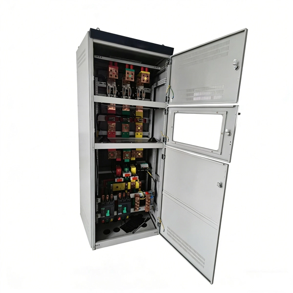
Protective relays are special electrical devices used to detect faults in power systems and quickly disconnect faulty parts to prevent damage. These relays sense abnormal conditions like overcurrent, under-voltage, or short circuits and send a signal to circuit breakers to open the. Electromechanical protective relays at a hydroelectric generating plant. The relays are in round glass cases. The rectangular devices are test connection blocks, used for testing and isolation of instrument transformer circuits. In electrical engineering, a protective relay is a relay device. Protective Relay Definition: A protective relay is an automatic device that senses abnormal conditions in electrical circuits and triggers actions to isolate faults. Types of Protective Relays: Protective relays are categorized by their mechanism (electromagnetic, static, mechanical) and function. Combines protection, sensors, control power, and circuit breaker in a single package Typically added to a breaker close circuit to prevent accidental reclosure after a trip. Three fundamental components required for each circuit breaker. It initiates the operation of circuit breakers to isolate the affected section.
[PDF]

A phase-sequence relay monitors phase rotation in three-phase systems, protecting equipment from damage due to incorrect or reversed phase order. It guards a 3-phase device against any potential damage due to sequence change. They are deployed anywhere with a phase-sequence change that can damage the device or circuit. They work like a conventional electric relay. The order of these voltages is typically designated as ABC, where A, B, and C represent the phases. The correct phase sequence is vital for proper functioning and protection of various. Engineers use a Phase Failure Relay, which is additionally known as a Voltage Monitoring Relay (or) a Phase Sequence Relay to avoid costly breakdowns. This small but powerful equipment continuously monitors the state of the three-phase supply & guarantees that motors work only according to safe. A phase sequence relay is a tool that controls the correct sequence of phases in three-phase electrical systems. It is basically a special type of protective device that is used to monitor and control the sequence or order in which the phases of a three-phase power supply are connected. The primary function of a Phase.
[PDF]

At its core, an overcurrent relay operates on a very simple concept: detect excessive current, then trip fast and isolate the fault. When current surpasses the relay's pickup setting, an internal mechanism triggers the circuit breaker. IEEE/IAS/I&CPSD Protection & Coordination WG Chair Jacobs Canada, Calgary, AB rasheek. com IEEE Southern Alberta Section PES/IAS Joint Chapter Technical Seminar - November 2016 Protective Relays - Technical Seminar Nov 2016 - Copyright: IEEE 2 Abstract: Protective relays and devices. Relay protection against high current was the earliest relay protection mechanism to develop. From this basic method, the graded overcurrent relay protection system, a discriminative short circuit protection, has been formulated. Types of over current relay. It is really current monitoring relay. Overcurrent Relay Definition: An overcurrent relay is a protective device that operates solely based on current without the need for a voltage coil. These relays are known for their speedy operation during a fault and are hence used widely in high-voltage applications. Let's know in. The Art and Science of Protective Relaying, by C. Mason, John Wiley and Sons, 1956. Evaluation of Distribution System Relaying Methods, by A. McConnell, Presented at the Pennsylvania Elec-tric Association, May 16-17, 1957.
[PDF]
Distance relays, also known as impedance relay, differ in principle from other forms of protection in that their performance is not governed by the magnitude of the current or voltage in the protected circuit but rather on the ratio of these two quantities.OverviewIn, a protective relay is a device designed to trip a when a is detected. The first protective relays were electromagnetic devices, relying on coils operating on moving par. Electromechanical protective relays operate by either, or. Unlike switching type electromechanical with fixed and usually ill-defined operating voltage thresholds. Electromechanical relays can be classified into several different types as follows: "Armature"-type relays have a pivoted lever supported on a hinge or knife-edge pivot, which carries a moving contact. These relays may.
[PDF]
Home appliances TV sets, VCR, Microwave ovens Office machines Industrial equipment NC machines, Robots, Temperature controllers Photocopiers, Vending machines. Space saving design Wiring can be done with ease (DIN terminal). N.C. contact raw N.O. contact raw COM contact raw Coil terminal raw. N.C. contact raw N.O. contact raw COM contact raw Coil terminal raw. For Cautions for Use, see Relay Technical Information.
[PDF]
of relay protection coordination for a PV power plant connected to the distribution network is presented. In recent years, installation of PV power plants in the distribution network has increased significantly. I.
[PDF]

Protective relays are essential devices used in electrical power systems to detect faults and abnormal conditions, initiating corrective actions to prevent equipment damage and ensure system stability. These relays play a crucial role in the protection of transformers, generators, transmission. A protective relay is an intelligent device that senses abnormal electrical conditions, such as overcurrent, under-voltage, or frequency deviations. It initiates the operation of circuit breakers to isolate the affected section. This prevents damage to equipment, reduces downtime, and safeguards. Protective relays are critical components in power systems, providing essential protection for various elements such as generator sets, outgoing feeder and load networks, and incoming utility sources. It functions as a watchdog by constantly surveying multiple system components including voltage, current, frequency, and phase angle. It. Protective relays and devices have been developed over 100 years ago to provide “lastline”of defense for the electrical systems. They are intended to quickly identify a fault and isolate it so the balance of the system continue to run under normal conditions. The selection and applications of.
[PDF]

This guide describes the general requirements, functional and technical performance requirements, test requirements, labeling and packaging requirements, transportation and storage requirements, supply integrity requirements, and quality assurance requirements for hybrid high-voltage. This guide describes the general requirements, functional and technical performance requirements, test requirements, labeling and packaging requirements, transportation and storage requirements, supply integrity requirements, and quality assurance requirements for hybrid high-voltage. Guide for Technical Requirements for Hybrid High-Voltage Direct Current Transmission Protection and Control Equipment This guide describes the general requirements, functional and technical performance requirements, test requirements, labeling and packaging requirements, transportation and storage. purpose of this white paper is to aid WECC members (Specifier) in specifying and applying relay systems that will provide adequate protection of extra-high voltage (EHV) on 345-kV or higher transmission lines and comply with the NERC Reliability Standards. The recommendations in this white paper.
[PDF]

Traditional electromechanical relays rely on fixed settings that cannot adapt to variable grid conditions. This often results in miscoordination, delayed fault clearing, or unnecessary tripping, compromising reliability. able sources such as wind and solar. These clean energy sources, connected through inverters and flexible transmission systems, are transforming traditional grids based on synchronous generators into more flexibl cant challenges to system stability. Nowhere is that clearer than in the challenge to. Relay protection systems are essential in maintaining the safety and reliability of modern electrical grids. As technology advances and grids become smarter, the tools used to test and maintain these systems, such as the relay test set, are evolving to meet new challenges. This article explores the. By taking a series of countermeasures, the paper explored the influence of new energy connection on traditional relay protection systems in response to the occurrence of the above phenomenon. These countermeasures include protection logic and settings optimization, fast fault detection technology. Abstract—This paper discusses the impact of inverter-based resources (IBRs) in traditional digital protection relays applied in the interconnection transmission line between the IBR and bulk power system. This paper explores the development of relay protection technology in smart grids, analyzing.
[PDF]
The CUBOmini 100G ODD is a multi-tool for 100G applications. It can be used as a demarcation device, repeater or media converter just to name a few. The CUBOmini is auto-sensing and requires no configuration to have an up and running fiber. Nokia's suite of vertically integrated intelligent coherent pluggables offers network operators the performance, scale and efficiency critical to drive down network operating costs and enhance service agility. Our Infinite Capacity Engine – Extensible (ICE-X) 100G and 400G transceivers support. mpact, stand-alone optical demarcation device for 100G. It is s 8 transceivers covering different distances up to 80km. It has two QSFP28 slots implemen ing a layer 1 optical conversion between the two slots. This approach not only makes the setup simple “plug & play” but also enables full. Arista supports a full range of 100G copper cables and optical transceivers compliant to IEEE standards and industry MSAs. It is specifically designed to solve a multitude of challenges. The CUBO mini is the first device to take advantage of the wide variety of 100G QSFP28 transceivers covering different distances up to. HUBER + SUHNER Cube Optics has launched its new Optical Demarcation Device (ODD), the CUBO mini 100G ODD. CUBO mini provides low latency, layer 1 "conversion".
[PDF]
At 200Mbps, there's a 3x price difference between the highest and lowest options. 5x) but much larger on a dollars basis - $496 to $1,256 monthly. Implementing Cisco SD-WAN Solutions (SDWAN300) v1. Subscription: MSLA Use ONLY. Cisco ISR 1100 Series SD-WAN IOS XE Universal. 12 IPB. Holiday calendar & working hours in the Baltics and Iceland. Transparency is the key to being trusted. Find the related documents regarding the rules, regulations and compliance of Nasdaq CSD's operations. Envision a Future – Fueled by Innovation, Technology, and Expertise. Leaders of diverse. TeleGeography's SD-WAN Pricing platform delivers pricing data and analysis on software-defined wide area network services around the world. Put licensing into operation. Access self-service or agent support. Need help?. A customs duty is a state tax imposed by EU law that a person or company must pay on goods imported into the European Union (import duties) from third countries (non-EU countries). Customs duty rates are set on the basis of the common commercial policy of the Union and the rates depend on the. FortiGate-200G 10 x GE RJ45 (including 1 x MGMT port, 1 x HA port, 8 x switch ports), 4 x GE SFP slots, 8 x 5GE RJ45, 8 x 10GE SFP+ slots, NP7Lite and CP10 hardware accelerated. Call For Lowest Price! Call For Lowest Price! Call For Lowest Price! Call For Lowest Price! Click here to jump to more.
[PDF]
Explore 49 top manufacturers and suppliers of Fiber Optic Passive Components in our comprehensive photonics buyers' guide. Fiber optic passive components are devices used in fiber optic communication systems that do not require an external power source to operate. Optipow excels in delivering innovative fiber optic solutions across multiple industries. These components serve various. Pump combiner is built based on fused biconical taper (FBT) technique, widely used in fiber laser,can be designed to meet a wide range of power handling configurations, number of input fibers and adaptation to different fiber types. A series of small-sized TGG isolators and circulators A. The Maxcom Coexistence mux allows systems to offer a combination of services over single fiber FTTx archetectures. These external muxes support a combination of E or GPON, XG (S)PON, and RF Overlay. Most are available with SM or PM fiber at 1550, 1310, or 1064nm wavelengths. The passive component product group includes SM and PM couplers (split light at specified ratios), polarization beam combiners/splitters (combine or. HyOptic is Passive Optics Manufacturer with 15 years OEM ODM experience, has leading edge Hybrid Optical Solutions and Micro-optics Technology which help customers win future market and help customers save 20% cost by continuous improving technology and productivity instead of lower quality, supply.
[PDF]
This guide provides a detailed, professional procedure for installing a Residual Current Circuit Breaker (RCCB)—a device essential for protecting people from the severe danger of electric shock. The steps outlined here are fundamental to ensuring the RCCB functions. It is an electrical protective device that protects electrical circuits and devices from some electrical faults such as leakage faults, electrical shock, current unbalance due to equipment failure, etc. It works on the principle of sensing residual current which is why it is called a residual. Distribution board is a safe system designed for house or building that included protective devices, isolator switches, circuit breaker and fuses to connect safely the cables and wires to the sub circuits and final sub circuits including their associated Live (Phase) Neutral and Earth conductors. Residual-current devices, commonly referred to as RCDs, are used in many practical applications. They can be found in fuse boxes, electrical switchgears or industrial machine control systems. Therefore. To wire an RCD fuse box correctly, start by reviewing the diagram to identify each circuit and its corresponding components. Understanding the layout helps prevent mistakes and ensures safe wiring. floor in a multi storey building. The Sub distribution board is connected and supplied from the Main Distribution Board through different wires and cables rated.
[PDF]


