On average, commercial projects range from $5,000 to $20,000 per mile underground and $40,000 to $60,000 per mile for aerial deployment. Individual business connections often cost between $15,000 and $30,000 for 100–200 network drops. Buying fiber optic installation services involves several cost components, with total price influenced by length, location, and access. The main cost drivers include trenching or aerial deployment, materials, labor hours, and any required permits. This guide presents typical price ranges in USD to. The initial cost of installing fiber optic cables can vary depending on the chosen installation method and specific project requirements. In preparing this second edition of the Fiber Deployment Cost report, Cartesian gathered inputs from a wide variety of firms building. Getting accurate cost estimates is crucial for winning fiber installation bids. Smart contractors know that underground vs aerial installation pricing varies wildly based on location and project conditions. This breakdown gives you real numbers to build better estimates. We'll show actual costs for. Home and business buyers typically see a wide range of costs for fiber optic projects, driven by distance, fiber type, conduit needs, and labor. The price can shift based on underground vs. aerial routes, equipment choices, and whether new permits are required. Some variables are less determinate.
[PDF]

This video shows you how to build a 10Gbps fiber optic network between buildings using PoE+ switches, SFP+ transceivers, and link aggregation for even higher speeds (up to 40Gbps!). Modern network infrastructure depends on fiber aggregation switches to combine several fiber optic links into one streamlined network connection. They are built to handle large amounts of data flowing through them without interruptions over long distances. more Need to transfer. With AXIS D8308 Fiber Aggregation Switch you can connect multiple Axis devices using fiber midspans over long distances. It also enables easy expansion by simply adding more fiber or network switches. Long-distance installations often require fiber optic cables to connect different sites because of. The Cisco ASR 920 Series Aggregation Services Router is a family of fixed configuration routers that enables Service Providers to provide business, residential, and mobile access services to their users. It is the Carrier Ethernet access platform providing Ethernet services. The Cisco ASR 920. This manual provides detailed instructions for the installation, operation, and maintenance of the Ubiquiti Networks UniFi Aggregation Switch, model USW-Aggregation. Fibers in these points are either spliced.
[PDF]

Fiber-optic cables are made by taking an individual fiber or bundle of fibers and adding coating and protective layers. A TOSLINK optical fiber cable with a clear jacket. These cables are used mainly for digital audio connections between devices. A fiber-optic cable, also known as an optical-fiber cable, is an assembly similar to an electrical cable but containing one or more optical fibers that are used to carry. A fiber optic cable consists of five basic components: the core, the cladding, the coating, the strengthening fibers, and the cable jacket. When searching for a fiber optic cable, we need to pay attention not only to the connectors, such as SC to ST fiber cable, LC to SC fiber patch cable, or SC to. Data transfer and telecommunications have been transformed by optical fiber technology. It consists of tiny glass or plastic fibers that can carry data as light pulses. The first low-loss optical fiber was created in 1970 by Robert Maurer, Donald. At its simplest, a fiber optic cable is a hair-thin strand of incredibly pure glass designed to transmit information using light pulses instead of electrical signals. This fundamental difference is why it's so fast and efficient. The process relies on a principle called Total Internal Reflection. The optical fiber transmits the signal, the strength member provides tensile and crush resistance, and the jacket protects the overall cable from the environment. Govind Agrawal, the Dr. Wyant Professor of Optics at the.
[PDF]

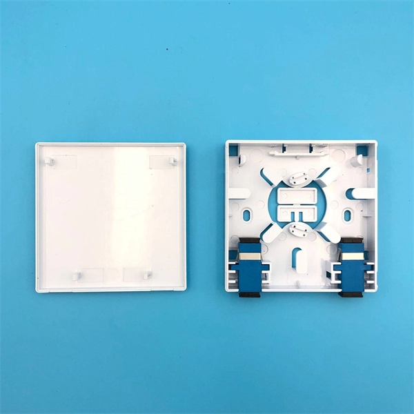
First, connect each pre-terminated fiber optic cable to the adapter panel separately, making sure the ports correspond one-to-one; then fix the fiber optic adapter panel to the front panel of the distribution box with the bend radius control clip. In general, installing the optical fiber distribution box can be divided into three steps: installing the optical fiber distribution box on the rack, introducing the optical cable into the optical fiber distribution box, and planning the optical fiber path in the optical fiber distribution box. The. Bottom installation: Select a proper installation position in the equipment room and drill four holes in the floor according to the dimensions shown in the manual. Fix the rack to the ground with expansion bolts. Top installation: Dimensions of four connection holes on the top according to the. The Optical Distribution Box (ODB) is high-density 2-in-2-out fiber box solution. Designing with a compact size of 340x220x100mm, the cabinet accommodates 1x2,1x4,1x8 and 1x16 etc. The 4 ports are sized for main cable from 9 to 16mm in diameter, along with 16 3mm cables. Accessory Kits:. Install the optical fiber distribution box on the rack. Ensure that the box is installed firmly and horizontally, and the deviation of perpendicularity is not greater than 3mm.
[PDF]

On average, you can rent a Fusion Splicer for $275/day, $773/week, $1424/month. The price of these splicers can be higher because of their mechanical complexity and ability to handle various fiber types, including large-core fibers. Hybrid splicers bring in various features that are present in both automatic splicers and manual splicers. They can be aligned by the core. Fiber optic fusion splicers are critical tools for deploying and maintaining fiber networks, with significant variations in performance, features, and pricing. This guide breaks down the key cost-influencing factors across five dimensions—splicer types, technology, performance, accessories, and. A fiber optic splicing machine is a specialized machine used to fuse two optical fibers together to form one long one. The machine, also known as a fiber optic fusion splicer, uses electricity to melt the two optic cables into one. The fiber fusion splicer conducts the fusion with high accuracy to. Check each product page for other buying options. Get reliable equipment with fast splicing times and comprehensive accessories included. It features a mini handheld design, integrated buttons and touch screen, simple operation, low.
[PDF]
These screws should be 1 to 1. 5 inches long to penetrate the box and embed into the center of the stud without protruding out the back. When attaching boxes to metal studs, the preferred fastener is a self-tapping or self-drilling metal screw, such as a #6 or #8 size with a pan or. These screws should be 1 to 1. All sorts of grounded electrical metal things are mounted with self-drilling or self tapping screws that do not have 32 threads. Leviton Comment: We are covering Articles 312. 10 Screws or Other Fasteners. Screws or other fasteners installed in the field. The length of the device screw varies based on the box depth and its recess from the finished wall surface. Standard installations often use screws between 1/2 inch and 3/4 inch long, but deeper boxes or those requiring adjustment spacers may necessitate screws up to 2 inches. Using a machine screw. These standard metal boxes have been secured by driving self-tapping screws through the 1/8-inch diameter mounting holes in the side of the box and into the horizontal metal stud. Code Change Summary: Changes were made to the. My plan to ground the outlet is to use a self-tapping metal screw fixed to the back of the box. Is this a proper method of connecting the outlet ground. The old boxes have tiny threaded holes at the front of the box, but they are too small for a standard machined ground screw. The threads are a 10/32" size thread. The 4020513001K.
[PDF]

This article will give you an overview of the use cases for fiber-optic networking, some of the terms used in fiber networking, and suggestions for setting up a fiber network. Once you understand the basic concepts, you can check out my Recommended Equipment section toward. Fiber tapping is a network tap method that extracts signal from an optical fiber without breaking the connection. Tapping of optical fiber entails diverting some of the signal being transmitted in the core of the fiber into another fiber or a detector. Fiber to the home (FTTH) systems use beam. Optical fiber is a technology used to transmit data by sending short light pulses along a long fiber, which is typically made of glass or plastic. In optical fiber communication, metal wires are preferred for transmission because the signals travel more safely. Optical fibers are also resistant to. Photo: Light pipe: fiber optics means sending light beams down thin strands of plastic or glass by making them bounce repeatedly off the walls. This is a simulated image. Note that in some countries, including the UK, fiber optics is spelled "fibre optics. " If you're looking for information online. This manual covers everything about fiber optic cables, how they work, where they are used, and what is new in this area of technology. The choice of fiber optic cable depends on the specific needs of the application, as well as the.
[PDF]
The good news is that network cabinet prices range from as low as $100 for basic wall-mounted units to over $3,000 for specialized outdoor models. However, understanding what drives these costs will help you make a smart buying decision. In this complete guide, we'll break down everything you need. Check each product page for other buying options. VEVOR 6U Wall Mount Network Server Cabinet, 15. 5" Deep, Server Rack Cabinet Enclosure, 200 lbs Max. 5". Explore our top-tier selection of Networking Cabinets and Racks designed to keep your IT infrastructure organized and secure. Whether you're setting up a home lab, a corporate data center, or managing network equipment for a small business, our collection offers robust and versatile solutions. Cabinets are used for storing routers, patch panels, switches and a wide variety of networking equipment and accessories. Network cabinets support large, modular network switches by providing additional space for cable management and. Network cabinets are enclosed systems designed to securely store, organize, and protect networking and IT equipment such as switches, routers, patch panels, servers, power strips, and cable management components. They allow users to secure their data and communication connections. The product will be reserved for you when.
[PDF]

An ideal optical splitter will distribute the light power according to mathematical principle. This is because each of the 8 output ports of the splitter will receive only one-eighth of the. Thorlabs' Single Mode 1x8 Fiber Optic Planar Lightwave Circuit (PLC) Splitters allow a user to split a single input signal evenly into eight output signals, which is ideal for passive optical networks (PON) and other high-channel-count applications. 1×8 splitter means it takes one input fiber and splits the signal into eight outputs. It doesn't need power — it's passive! Great for sharing one signal with many devices, like in FTTH (Fiber To The Home) networks. But light doesn't just split for free. Sharing means each output gets less than the. If we operate with absolute gains measured in relation to 1 milliwatt (mW), they are expressed in dBm, and are calculated as follows: Power Level (dBm) = 10 lg ( mW / 1 ) For “household” needs, in order not to calculate mW to dBm and vice versa every time, here's a ready-made correspondence table:. For instance, a 1:8 splitter ratio signifies an equal distribution of incoming optical power among eight output ports, with each port receiving 1/8th of the total power. It has one input port and eight output ports, making it ideal for applications where a signal needs to be.
[PDF]

This guide covers the critical steps, from selecting the right electrical cable tray and performing accurate cable fill calculations to managing a safe cable pull through and ensuring all bonding and grounding requirements are met. Article Summary: A compliant cable tray installation requires a thorough understanding of NEC Article 392, proper structural support, and precise installation techniques. Structural building members should never be cut, and cable trays should not be installed in hoist ways or where subject to physical damage. Cable tray systems re to be installed so that they are accessible. Here is a step-by-step guide on how to install a standard metal cable tray system (e., ladder or perforated type). But before you lay the first tray or clamp down a single cable, you need a solid plan. When ofloading tray from a flat deck trailer using an overhead crane, care should be exercised in the placement and length of the slings to prevent crushing the product (siderails). Only ofload. Cable tray systems are designed for easy installation and to accommodate power, communications, and signal cabling across a variety of applications. When properly installed, cable trays prevent damage to cabling and the area's structural integrity. When installed and engineered properly, cable.
[PDF]

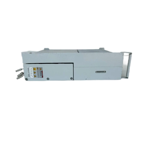
It transforms high volumes of electrical signals into optical signals for transmission over fiber cables, or reverses the process at the receiving end. Think of it like a Type-C to USB adapter in everyday tech—its core function is seamless conversion between electrical and optical. Optical modules are compact devices that convert electrical signals into optical signals and vice versa. They are used in fiber optic communication systems to transmit data over long distances with minimal loss and interference. These modules typically consist of a laser or LED transmitter, a. In the world of fiber optic communications, optical transceiver modules play a pivotal role as interfaces that convert electrical signals to optical signals and vice versa. An optical module works at the physical layer of the OSI model and is one of the core components in the fiber communication. The frequency response characterization of these electrical-to-optical (E/O, modulators sometimes integrated with lasers) and optical-to-electrical (O/E, photo detectors and receivers) converters can be important in terms of such parameters as bandwidth, flatness, phase linearity and group delay. The optical module serves as a crucial component in optical fiber communication systems, operating at the physical layer, which is the lowest layer in the OSI model. Among various optical module form factors, SFP (Small Form-Factor Pluggable).
[PDF]
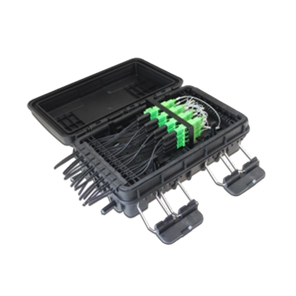
Learn how to splice 4-fiber optic cables using ODF in this complete step-by-step tutorial. Whether you are a beginner or a professional in fiber optic networking, this guide will help you splice fiber cables accurately, manage connections with ODF panels, and ensure. This complete guide explores everything you need to know about ODFs — from their structure, types, and key components, to installation best practices and modern design trends. Whether you're building a central office, data center, or FTTx distribution network, understanding the right ODF. How to Splice 4-Fiber Optic Cable with ODF | Step-by-Step Fiber Optic Splicing Tutorial. This guide demystifies ODF, exploring their design, core functions, types, and how they. An Optical Distribution Frame (ODF) is the central hub for fiber splicing, termination, patching, and cable protection in modern optical networks. It's where incoming and outgoing cables meet. It does four key things: Think of it as the central hub for your fiber network. Without it, cables get tangled. This article explores the types, components, applications, installation, and maintenance best practices, providing a.
[PDF]
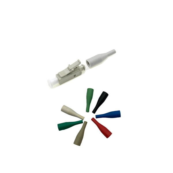
As light in fibers often does not have a well defined polarization state, it is important that a fiber-optic attenuator exhibits only a minimum amount of polarization dependence. Generally, the obtained insertion loss has some dependence on the optical wavelength. Some attenuators have a relatively strong wavelength dependence and are made for working in narrow wavelength regions, e.g. with a bandwidth of only 20 nm around a center wavelength of 1550 nm. Others are optimized for a weaker wavelength dependence, making them u. For single-mode devices, the insertion loss can not depend on the direction of propagation, as long as no non-reciprocal parts are used, as e.g. in a Faraday isolator. For multimode devices, however, some loss difference is possible in conjunction with a mode dependence. For many applications, it will not be a problem if the obtained insertion loss slightly deviates from the specification (e.g. by 1 dB), or if it slightly changes over time. Example cases, however, one may require a higher precision. Most fiber-optic attenuators exhibit a relatively high return loss (at least several dozens of decibels), i.e., there is not much light which is reflected back into the input fiber. For some sensitive applications, e.g. when using an attenuator before or after a high-gain fiber amplifier, one may have two use attenuators with particularly high retu.
[PDF]