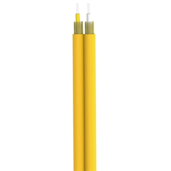
BiDi SFP+ changes the geometry: each module uses a single fiber pair directionally separated by wavelength, so you can run one strand where you previously needed two. One of the most common decisions network engineers face is selecting between single fiber SFP and dual fiber SFP modules. This comprehensive guide explores the differences between single and dual fiber SFPs, their respective benefits, limitations, and use cases—helping you make an informed choice. A single fiber SFP, also known as a BiDi SFP, is designed precisely for this purpose—enabling bidirectional data transmission over a single strand of optical fiber. Unlike traditional SFP transceivers that require two fibers—one for transmitting and one for receiving—a single fiber SFP uses. SFP (Small Form-factor Pluggable) is a compact, hot-pluggable network interface module used to connect network devices (switches, routers, firewalls) to fiber optic or copper cables. An SFP interface on networking hardware is a modular slot for a media-specific transceiver, such as for a fiber-optic cable or a copper. Both transmitting and receiving need one optical fiber to connect. Simplex SFP modules, also known as BIDI transceiver, employs a unidirectional transmission mechanism and have only one port. In practice, that means fewer splice points, smaller patch panels, and less conduit congestion—especially in retrofit buildings.
[PDF]
WDM, CWDM and DWDM are based on the same concept of using multiple wavelengths of light on a single fiber but differ in the spacing of the wavelengths, number of channels, and the ability to amplify the multiplexed signals in the optical space.OverviewIn, wavelength-division multiplexing (WDM) is a technology which a number of signals onto a single by using different (i.e., colors) of. A WDM system uses a at the to join the several signals together and a at the to split them apart. With the right type of fiber, it is possible to have a device that does both s. Originally, the term coarse wavelength-division multiplexing (CWDM) was fairly generic and described a number of different channel configurations. In general, the choice of channel spacings and frequency in these co.
[PDF]

Perform a dielectric strength test to check the insulation properties of the busbars under high voltage conditions. The Partial Discharge test is crucial for determining long-term part. A busbar protection must be capable of clearing all phase-to-earth faults, and in the case where they can occur, phase-to-phase faults. Policy regarding fault clearance times required from busbar protection varies from utility to utility. Due to the fact that the short-circuit levels of bus bars. Early detection of cracks is crucial for preventing. Check the mechanical. The voltage of the faulted phase decreases (in case of incomplete grounding) or drops to zero (in case of solid grounding). In stable grounding, the. Busbar Differential Protection Definition: Busbar differential protection is a scheme that quickly isolates faults by comparing currents entering and leaving the busbar using Kirchoff's current law. Current Differential Protection: This protection method connects CT secondaries in parallel and. That's based on air insulated buswork well above your head and a reasonable set of remote zone 2 times. I agree with you as chances of surviving a bus fault is practically non existent at 110/220kV regardless if its cleared in ~100ms via busbar prot scheme or via remote end in zone 2 times of.
[PDF]
An optical module is mainly composed of optoelectronic devices (including the optical transmitter and optical receiver), functional circuitry, and optical interfaces. Its fundamental role is to bridge the gap between electrical equipment and optical fibers. Optical modules are key components in fiber optic communication systems, responsible for electro-optical conversion, meaning the conversion of electrical signals to optical signals or vice versa. The internal structure of an optical module is complex but can be divided into several main parts. As an essential component of optical fiber communication, optical modules are optoelectronic devices that facilitate the conversion between optical and electrical signals during the transmission process. Operating at the physical layer of the OSI model, optical modules are core devices in optical. This comprehensive guide breaks down the internal structure, core components (TOSA, ROSA, lasers), and operational mechanisms of SFP optical modules, enriched with technical insights and real-world applications. It is available in TO-CAN, Gold-BOX, COC (chip on chip), COB (chip on board), and other packaging forms. This article will introduce you to the.
[PDF]

This article documents how we paired an EDFA optical amplifier transceiver strategy with transport modules to stabilize signal margin across changing span loss. This installation note provides the installation instructions for the Cisco small form-factor pluggable (SFP) and SFP+ transceiver modules. It helps network and procurement teams compare options, control lead time, and reduce supply chain risk without sacrificing link. This section describes how to install optical transceivers on the SFP or SFP+ ports and connect them to the ports of the peer device using optical fibers according to the network plan. The USG supports both 1 Gbit/s, 10 Gbit/s, and 40 Gbit/s optical modules. The optical modules at both ends are. In the world of fiber optic communications, optical transceiver modules play a pivotal role as interfaces that convert electrical signals to optical signals and vice versa. These standardized devices convert electrical signals from network equipment. Every piece of data traveling across a fiber optic network passes through an optical transceiver.
[PDF]

The Bridge Module (BRG) connects two Bently NevadaTM Orbit 60 Chassis together by connecting the bridge of one chassis to the bridge on another chassis forming a single Orbit 60 system. Two bridges can be installed in each chassis to provide redundant capability. Bridge ONU gives you more control over your network. You can use your own router and change settings how you like. Router ONU does the job of both an ONU and a router. It lets. Optical modules are devices used to connect network devices, transmit and receive data between network devices, and can be used to convert optical and electrical signals. The optical module is a very important component in an optical communication system. This article will introduce you to the. Optical transceivers have revolutionized data transmission, providing high-speed, long-distance, and secure data transmission capabilities. Optical transceivers have enabled the development of high-speed networks, such as 10 Gigabit Ethernet, 40 Gigabit Ethernet, 100 Gigabit Ethernet, and beyond. A maximum of two chassis can be. Small Form-factor Pluggable (SFP) optical modules, with their compact size, versatile applicability, and high-performance transmission capabilities, have become dominant players in contemporary communication networks. This article dives deep into the fundamental principles, technical features.
[PDF]

An optical transceiver module, often simply called an optical module, acts as a signal conversion interface in fiber optic networks. It transforms high volumes of electrical signals into optical signals for transmission over fiber cables, or reverses the process at the receiving. As an essential component of optical fiber communication, optical modules are optoelectronic devices that facilitate the conversion between optical and electrical signals during the transmission process. Operating at the physical layer of the OSI model, optical modules are core devices in optical. An optical module is a typically hot-pluggable optical transceiver used in high-bandwidth data communications applications. Its primary function is to achieve optoelectronic conversion by converting electrical signals into optical signals and vice versa. If you're dealing with data centers, telecommunications, or AI networking, grasping the key parameters of an optical. What is an Optical Module? The Ultimate Guide to Principles, Types, and Troubleshooting Optical Modules (also known as Optical Transceivers) are critical components in fiber optic communication systems. Among various optical module form factors, SFP (Small Form-Factor Pluggable).
[PDF]
The high-voltage SiC MOSFET power modules enable high-frequency and high-efficiency power conversion. The parasitic inductances induced by traditional packages of this device technology significantly d.
[PDF]

The IDC Indus smart/connected device module works using a low cost 868 proprietary network and can be adapted for new and emerging standards such as LoRa. It is suitable for use in domestic, office and industrial environments. The iPDU-MC series rack iPDU is designed to suit the operational requirements of next-generation datacenters. iPDU-MC series iPDUs. Clients can benefit from our IoT expertise by using our proven, ready-made IoT modules to save development time, cost and risk. We stock a large selection of IDC Connectors, including new and most popular products from the world's top manufacturers including: TE Connectivity / Partner Stock, TE Connectivity - Amp, 3M, Amphenol Communications Solutions & Wurth Elektronik. The Euro Module range from British General allows you to build your own configuration from a wide a variety of interchangeable modules plates and finishes. This black master telephone module uses an IDC terminal connection, and should be used where your telephone line enters your property. If you. 1. A range of IDC connection modules from TUK that are fully compatible with Commscope (Krone) LSA-Plus and other similar designs. The Cat6 outlet supports data transfer speeds of up to 10Gbps at 250MHz.
[PDF]

Jabil Photonics General Pluggable Platform (GPP) is an optical transmission platform with strong versatility, available in 1RU or 2RU variant, capable of hosting different service cards like amplification and optical MUX. Remote configuration and monitoring is possible with SNMP MIB and graphical. Help others learn more about this product by uploading a video! Would you like to tell us about a lower price?. The SFP+ SR module electrical interface is compliant to SFI electrical specifications. The transmitter input and receiver output impedance is 100 Ohms differential. Data lines are internally AC coupled. The module provides differential termination and reduce differential to common mode conversion. Availability : 2 pc. All products purchased in our store come with a one-year warranty against manufacturing defects. The warranty begins on the date of purchase and applies to all items in our inventory. If you encounter any issues, please contact our customer service team for assistance. Remote configuration and monitoring is possible thank you to the support of SNMP.
[PDF]
We offer a wide range of OEM-compatible optical transceivers & cables, ensuring reliable, high-speed connectivity. The transceiver consists of three sections: a Cooled EML laser transmitter, a APD photodiode integrated with a trans-impedance preamplifier (TIA). As a professional optical transceiver manufacturer, Innoptical offers an extensive assortment of optical transceivers to fit your requirements. Ranging from low-data rate to 800 GB, our transceivers cover types of SFP, SFP+, SFP28, SFP56, QSFP+, QSFP28, QSFP56, QSFP-DD, OSFP, GPON OLT transceivers. Product Specifications/Features SFP Optical Transceivers are hot-swappable, compact media connectors that provide instant fiber connectivity for your networking gear. They are a cost effective way. The optical transceiver is designed for use in 100/155Mbit/s data links. It provides the SC. The LS-SM312G-40C SFP transceivers are high performance, cost effective modules supporting data rate of 2. 5Gbps and 40km transmission distance with SMF. By seamlessly integrating advanced silicon photonics, ultra high speed circuit and packaging designs, Hyper Photonix offers a comprehensive range. Through lean management, manufacturing and our Source Lean Quality (SLQ) system, we run our world-class operation at maximum efficiency, identifying and eliminating waste in our processes to create more value for our customers. Our technical expertise in R&D runs deep with manufacturing process.
[PDF]

This product provides four channels of optical isolation with both a non-inverting output and an inverting output for each channel. Both the input side and the output side are designed to interface with equipment using logic voltages o. This product provides four channels of optical isolation with both a non-inverting output and an inverting output for each channel. Both the input side and the output side are designed to interface with equipment using logic voltages of anywhere from 3.3V to 24V. This robust design includes low-side output drivers that provide significant sink curr. The original OPI104 variant (OPI104-DIN, OPI104-FT) utilizes an output stage which includes current limit and thermal limit features, but whose output switching speeds are slower due to the protection circuitry. Due to present supply chain delays for the protected output stage components, we have introduced a new variant which uses a standard outpu. Pricing and Ordering All of the above items are normally stocked. Please call us if you need to verify availability for a specific quantity, or for pricing at higher quantities. Please visit our ordering pagefor our ordering policies and a list of ordering methods.
[PDF]
The Lightning Pick system is so intuitive and easy to understand that temporary workers can be effective with just a few minutes of training. Complex systems with steep training curves don't fit modern warehousing and order picking n. The Lightning Pick system is so intuitive and easy to understand that temporary workers can be effective with just a few minutes of training. Complex systems with steep training curves don't fit modern warehousing and order picking needs. Also, these systems are highly adaptable, so they evolve along with your business. Light modules are easy to ad. When an SKU must be picked from a specific location, the right indicator turns on to indicate action is required. The picker selects the quantity displayed and confirms the pick by pressing the lighted button. Light-directed picking systems can easily be configured to drive performance make picking more efficient for: 1. Fast, medium and slow velocity SKUs 2. Order picking, kitting and sortation 3. Full and split-case picking 4. Many popular picking methodologies such as zone picking, cluster picking, bucket brigade, batch picking, order consolidation, s.
[PDF]