They are designed to split unpolarized light at a specific Reflection/Transmission (R/T) ratio with unspecified polarization tendencies. A beam splitter or beamsplitter is an optical device that splits a beam of light into a transmitted and a reflected beam. It is a crucial part of many optical experimental and measurement systems, such as interferometers, also finding widespread application in fibre optic telecommunications. This division allows for the simultaneous analysis or utilization of the light's properties along two separate paths. The device is purely. Transmission and Reflection by. In addition to the task of dividing light, beamsplitters can be employed to recombine two separate light beams or. Explore the precision, applications, and design principles of beam splitters, essential for advancements in scientific research and technology. With WDS, a single X-ray energy – monochromatic X-rays – are counted at any given time. 19511; JEOL L-Value table2; CAMECA® SXFiveFE brochure3; Oxford Instruments Wave brochure4; Thermo ScientificTM NORANTM IbeX5). Unlike conventional beam splitters, PBSs ensure that the resulting beams are both linearly.
[PDF]

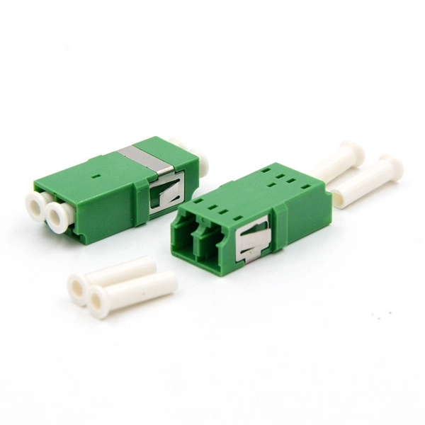
In all, there are five steps to manufacture a passive optical splitter. Each step requires strict control and management of various parameters like environment, temperature, and detailed precision on assembly and equipment. We will now provide a detailed introduction using PLC. A fiber optic splitter is a passive optical component that divides a single incoming optical signal into two or more outgoing signals, or combines multiple incoming signals into one. Unlike active devices (which require power), splitters operate without electricity, relying solely on the physics of. The Asia Pacific region (APAC) leads worldwide consumption of Planar Lightwave Circuit (PLC) splitter compact devices with a 68% share, followed by the Americas and the EMEA (Europe, Middle East, and Africa) region. The global PLC Fiber Optic Splitter market was valued at $4. 47 Billion USD in 2020. A fibre optic splitter like 1x2 Fiber Splitter is manufactured in five steps. Step 1: Component Preparation Generally, three components are required. The Evolution of Fiber Splitter Manufacturing Traditional fiber splitter production relied heavily on manual assembly and fused biconical taper (FBT) technology, which struggled to meet modern requirements for uniformity and miniaturization. It can divide the input optical signal into multiple output optical signals to meet the fiber optic access needs of multiple terminal devices.
[PDF]
Commonly, a power meter on its own is used to measure absolute optical power, or used with a matched light source to measure loss. When combined with a light source, the instrument is called an Optical Loss Test Set, or OLTS, typically used to measure optical power and end-to-end optical loss.OverviewAn optical power meter (OPM) is a device used to measure the power in an signal. The term usually refers to a device for testing average power in systems. Other general purpose light power measuring. The major types are (Si), (Ge) and (InGaAs). Additionally, these may be used with attenuating elements for high optical power testing, or wavelengt. A typical OPM is linear from about 0 dBm (1 milli Watt) to about -50 dBm (10 nano Watt), although the display range may be larger. Above 0 dBm is considered "high power", and specially adapted units may measure u.
[PDF]
An optical power meter (OPM) is a device used to measure the power in an signal. The term usually refers to a device for testing average power in systems. Other general purpose light power measuring devices are usually called,, power meters (can be sensors or ), or lux meters. A typical optical power meter consists of a , measuring and display. The sens.
[PDF]
Many U.S. exporters of consumer products will find that an agent/distributor arrangement is the most convenient and cost-effective mechanism for sales in Belize. Local distributors tend to have local mark.
[PDF]

Call Boxes are to be located no higher than 48” front reach or 54” side reach to the center of the button above ground level. Call Boxes must include braille identifying the unit as an “Emergency Phone”. An elevator electrical wiring diagram is a visual representation of the electrical connections and components of an elevator system. This diagram is essential. An elevator is a complex mechanical and electrical system that requires careful construction and precise wiring to ensure safe and efficient operation. The wiring. The purpose of this T/C is to clarify wiring that is permitted to be located in an elevator hoistway, machine/control room, or control space/room. Call Commander(s) shall be connected to designated ports on the Distribution Module. cabling used shall be RATH® Cable RP7500094B or. In Oregon, Raceways and conduits for the connection of elevator devices shall only enter the machine room to the extent necessary to connect the devices attached thereto. 37 covers wiring in hoistways, machine rooms, control rooms, machinery spaces, and control spaces related to the. Eaton's Elevator Control panelboards provide electric power distribution with integrated fusible switches, metering, and surge protection. Additionally, they're designed to meet UL 67 and NEMA PB1 standards for use in data centers, industrial, commercial and healthcare facilities.
[PDF]
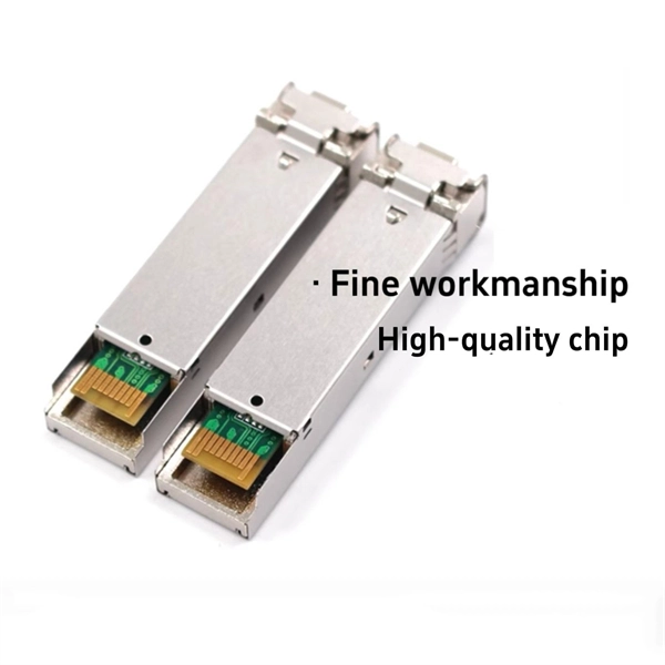
Laser diodes form a subset of the larger classification of semiconductor p – n junction diodes. Forward electrical bias across the laser diode causes the two species of charge carrier – holes and electrons – to be injected from opposite sides of the PIN junction into the depletion region.OverviewA laser diode (LD, also injection laser diode or ILD or semiconductor laser or diode laser) is a device similar to a in which a diode pumped directly with electrical current can create. A laser diode is electrically a. The active region of the laser diode is in the intrinsic (I) region, and the carriers (electrons and holes) are pumped into that region from the N and P regions respectivel.
[PDF]

These cables can be classified based on key parameters including fiber mode, fiber count, cable jacket rating, connector type, and end-face polish. There are different types of fiber optic cables because each type is optimized for specific applications that have unique requirements for bandwidth, transmission distance, and environmental factors. The choice of fiber optic cable depends on the specific needs of the application, as well as the. Fiber optic cables come in various types based on different specifications and application requirements. Unlike copper wires, which are limited by lower data transmission speeds, shorter transmission distances, and higher susceptibility to electromagnetic interference, fiber optic cables offer unparalleled performance and can. This quick guide will highlight the characteristics of OS2, OM1, OM2, OM3 multimode fiber, OM4, and OM5 fiber cables. The first difference to understand is the one that exists between OS and OM cables. The briefest explanation is that OS cables are all singlemode fiber, and OM cables are multimode. 801 is currently being finalized and should come into effect in mid 2010. It is eagerly awaited as it outlines the requirements for Category 6A components, but the amendment will also have significa c fibre optics used in industrial networks such as Interbus and Profibus. The second p nd AMD2.
[PDF]
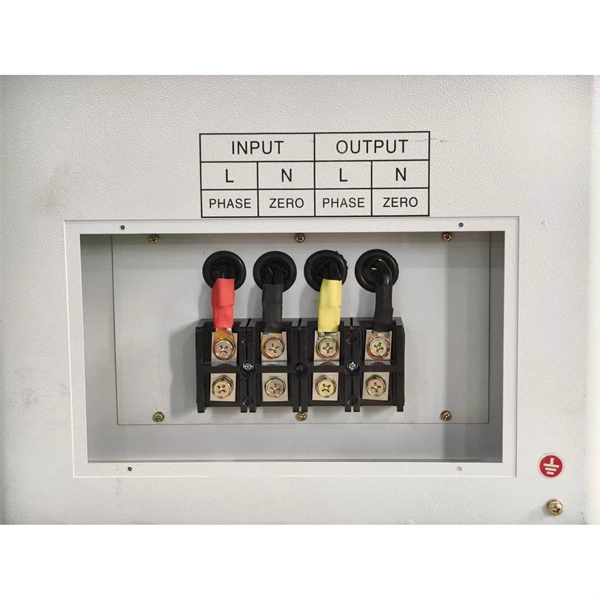
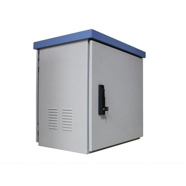
The main service panel is typically located in a home's basement or utility room. Some homes also have a subpanel—a smaller version of the main panel—to control electrical circuits in a garage, workshop, or other outbuilding. The National Electrical Code (NEC) does not specify a minimum height for an electrical panel, although practical access for service should always be considered. But there is a maximum height allowed for an electrical panel, which is based on the height of the highest breaker switch in the panel. NEC Article 408 covers switchboards, switchgear, and Panelboards installation and applications. Guidelines set by the National Electrical Code (NEC) provide a framework that ensures these installations adhere to stringent safety protocols. This article provides an exhaustive examination of the principles and standards governing the height at which electrical panels should be installed. The National Electric Code (NEC) includes the minimum standards for installing a circuit breaker panel box. These standards set the minimum safety standards for panel boxes. Tomorrow I'll be looking at a panel that was installed in a dining room knee wall 18" above floor. You can find electric panels inside cabinets, behind refrigerators, or inside clothes closets in older homes. Electrical panels.
[PDF]