
When a circuit breaker keeps tripping, the cause usually falls into one of three categories: overloads, short circuits, or ground faults. The key is knowing what's driving each one so you can troubleshoot it correctly. This comprehensive guide, compiled by ELECO's technical support team based on decades of global field experience, provides a clear, actionable roadmap to identify and solve the five most common causes of frequent tripping, saving you time and ensuring compliance on any international project. The bottom line: A tripping breaker means your electrical system is doing exactly what it's supposed to do. Now we need to figure out why. Understanding which one you're dealing with helps you know if this is something you can handle or if you need. Circuit breakers serve as your home's electrical guardians – they automatically cut power when detecting dangerous conditions. Occasional tripping is normal protection behavior, but frequent tripping signals underlying issues needing attention. It's a typical issue. Below, you'll find reasons why this occurs and tips to avoid it moving forward. Get a handle on your circuit breaker problems! Circuit breakers are protection.
[PDF]

In this guide, learn the basics of reading and interpreting electrical wiring diagrams. Follow Along on SkillCat: "Wiring Diagrams" Course! Want to test your knowledge? Skip to the quiz!. In this article, you'll learn how to read, understand and use a wiring diagram. An electrical wiring diagram could be a single page schematic of how a ceiling fan should be connected to the power source and its remote switches. A wiring diagram may include the wirings of a vehicle. For example, how. Electrical wiring diagrams are an essential tool for electricians, engineers, and automation technicians. Proper interpretation is crucial for understanding the operation of devices, diagnosing faults, and working safely with electrical installations. Understanding how to read electrical diagrams. In order to trace control system problems to the core, the ability to read and interpret various resources, from facility-level diagrams to machine-level wiring layouts, is critical. The engineering world is crammed full of drawings and diagrams of every possible kind. It shields sensitive equipment from dust, moisture, and. After reading and studying this handbook, electricians (or would-be electricians) will have a firm grasp on the many symbols used in electrical diagrams.
[PDF]

Mount individual circuit breakers in the designated positions within the distribution box. Each breaker should match the current rating and type required for its specific circuit. Ensure proper connection to the busbars and secure mounting to prevent loosening over time. When opening the distribution box, several different brands of circuit breakers are installed inside. It seems that the sizes match and the installation is fine, and this. The feeder amp rating is sized based on the sum of the amp rating of the largest branch protective device plus the full-load currents of the other loads. This value is added to the full load currents of the. Finding the right circuit breaker for your electrical panel is crucial to ensure safety, performance, and code compliance. Not all breakers are interchangeable across different panel brands – each manufacturer designs its breakers and panels as a matched system. Using a breaker that isn't made or. In industrial power distribution systems, cable distribution boxes (also known as power distributor boxes, distribution electrical boxes, or electrical power distribution boxes) are the core hub of power transmission, branching, and protection. You lower the chance of circuits getting too hot or overloaded when you pick the right box for your needs. A single circuit breaker installation mistake can cost your facility thousands in downtime, equipment damage, or worse—put lives at risk.
[PDF]

Circuit breaker wiring configurations involve organizing main switches, busbars, and branch breakers within a distribution box. Proper setups ensure balanced electrical loads, ground fault protection, and easy maintenance. Messy distribution boxes are dangerous and very hard to fix. This guide shows you how to organize circuit breaker wiring properly. You will learn to build a safe, efficient, and professional electrical system today. Location determination: Determine the installation position of the circuit breaker according to the position of the. The distribution board is the heart of every electrical installation. This guide covers split load vs dual RCD vs RCBO board configurations, circuit arrangement and allocation, BS 7671 labelling requirements, type testing under BS EN 61439, SPD installation, wiring best practice, and the common. Distribution panels, breaker panels, load center, and/or distribution boards—any name you call them, they're a key part of every electrical system. Wiring distribution panels serve as the central hub and nerve center, routing power from the main service feed to multiple circuits. When setting up. Hey, in this article we are going to see the Single Phase Distribution Box Wiring Diagram and Connection Procedure. It serves as a central hub for distributing electricity throughout a building, ensuring that power is delivered safely and efficiently to all the required locations.
[PDF]
An €80 million loan (equal to about XOF 52. 5 billion) from IFC and other investors will enable Orange Mali to install 300 new 4G towers and expand its fiber network to reach an estimated 300,000 households and smaller businesses in Mali. Mali's government has reportedly contracted China International Telecommunication Construction Corporate to extend the country's national fibre-optic network. According to Agence Ecofin, the work will be carried out as part of a USD117. To expand access to quality and affordable connectivity and. Bamako, Mali, November 17, 2025 — To expand access to quality and affordable connectivity and digital financial services in Mali, especially in rural areas, IFC today announced a partnership with Orange Mali SA to support the company to upgrade its infrastructure, expand broadband coverage, and. The Malian government seeks to strengthen the national telecom infrastructure as part of its digital transformation ambitions. The aim is to gradually include the 65% of the population who, according to DataReportal data, still lack access to the Internet. With a total cost of 117. 3 million USD, the project was approved by the Council of Ministers on Wednesday January 3.
[PDF]

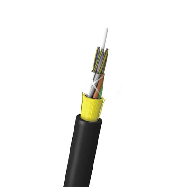
In this video, I walk you through my personal method of prepping and installing a 1:16 fiber optic splitter inside a sealed, weatherproof distribution box getting it ready for field deployment at a site. This is the way I've found to be clean, efficient, and reliable based on my experience in the. When employing the first-level splitting method in a residential network, optical splitters offer flexibility for indoor or outdoor installation. Indoor options encompass locations like the community's central computer room, building's weak current well, or floor wiring box. Optical cables can be. How to install the splitter distribution box is the important information we need to know. This article includes the following: 1. Install the fixture 2. Ground the installation system 1. Understanding Fiber Optic Splitter Box A fiber optic splitter box is a device used in fiber optic networks to split a single optical signal into multiple signals. This type of fiber optic cable splitter is generally placed in fiber splice closure or fiber splitter box. If plc splitter with connector, like bare splitter, mini plc splitter, there is a steel tube to protect the chip in the middle and the loose tube adhesion position. Have any questions? Talk with us directly using LiveChat.
[PDF]

RCCBs (Residual Current Circuit Breakers) should be installed in key areas of your home's electrical system for maximum safety. The best place to install an RCCB is in the distribution board (DB box), which controls the electrical circuits throughout your home. This location ensures that the RCCB protects the entire electrical system by monitoring the current flow throughout. For added protection, you can also. A residual-current device (RCD), residual-current circuit breaker (RCCB) or ground fault circuit interrupter (GFCI) is an electrical safety device, more specifically a form of Earth-leakage circuit breaker, that interrupts an electrical circuit when the current passing through line and neutral. The primary function of an RCD is to monitor the electrical current flowing in a circuit and quickly disconnect the power supply if it detects an imbalance current (leakage of current to ground) between the live and neutral conductors. An RCD is essentially a current-operated ELCB and is commonly. RCCB Definition: A Residual Current Circuit Breaker (RCCB) is defined as a safety device that detects and interrupts a circuit when there is a leakage current to the ground. It can swiftly disconnect the circuit when a fault current happens and prevent wiring damage. In this article, we explain what an RCBO is and how it.
[PDF]
High-definition temperature sensing based on the natural Rayleigh backscatter in optical fiber delivers a virtually continuous line of temperature measurements with sub-millimeter spatial resolution. 1. Map temperat.
[PDF]
A distribution box, or DB box, is a circuit breaker enclosure. It is a vital part and central hub of any electrical system. The hub distributes electrical power from a single input source to various circuits throughout a building. A distribution box, also known as a power distribution box or electrical distribution box, is used to distribute electrical power safely to multiple circuits. Distribution. A distribution boxes is an essential device that manages the safe and efficient flow of electrical power throughout different areas of a building or facility. Today, electrical systems are essential for homes and industries. It is widely employed in residential, commercial and industrial set-ups for circuit control and protection. By knowing their great.
[PDF]
The ring main circuit is commonly used for powering lighting circuits and plug sockets in residential and commercial buildings. It provides a safe and reliable method of electrical distribution, ensuring a consistent supply of power to each outlet. WATERPROOF DISTRIBUTION BOX: The power socket distribution box is made of high-quality ABS plastic material, with a size of 9. The waterproof grade of the shell is IP65. It is equipped with 4 IP44 waterproof sockets., can. The distribution box (DB box) helps safely and efficiently distribute electrical power. Today, electrical systems are essential for homes and industries. But what exactly is a power distribution box, and why is it so essential in our daily lives? The DB panel board controls the flow of electricity. Also known as a distribution board or breaker panel, it acts as the control hub, distributing power to different circuits and protecting them from overloads and faults. Here, we'll delve into what an electrical distribution box is, how it. Portable distribution boxes are mainly composed of core components such as shells, circuit breakers, sockets, terminals, leakage protectors, fuses, etc. As a protective "armor", the shell is mostly made of high-strength engineering plastics or aluminum alloys. Understanding the ring main circuit diagram is essential for electricians and individuals involved in electrical installations and repairs. The ring main circuit consists of a loop of cable, which.
[PDF]

This video shows real on-site footage of electrical installation, demonstrating safe and standardized wiring methods used by professionals. The National Electrical Code (NEC) Section 700. 10 provides critical guidelines for the wiring of emergency systems. These systems ensure continued operation during power outages, protecting lives and maintaining functionality in key buildings. This guide breaks down the essential requirements of. Emergency system circuits supply power to critical life safety loads such as emergency lighting, fire alarm systems, fire pumps, smoke control systems, and essential communication and control circuits. Correct wiring design for emergency system circuits is essential to maintain power integrity. The general rule in 700. 10 (B) is to keep wiring from an emergency source or emergency source distribution overcurrent device to the emergency loads entirely separate from all other wiring and equipment, unless otherwise permitted in 700. 10 (B) (1) through (5). 12) of the interruption of the normal electrical supply.
[PDF]
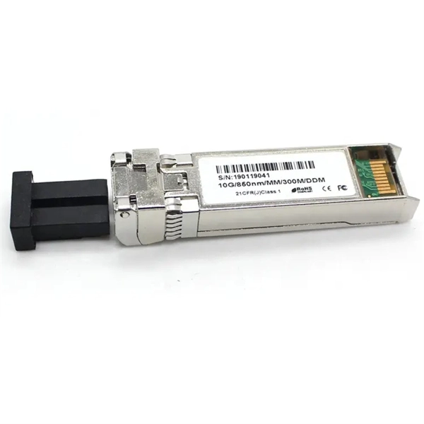
This comprehensive guide will explore the importance and benefits of this integration, provide an understanding of fiber optic cable and Ethernet ports, discuss their compatibility, and offer a step-by-step process for connecting them. Proper connection of fiber optic cables is essential to harness these benefits fully, as even minor errors can lead to significant performance issues like signal loss. This article will guide you through the necessary tools, materials, and methods on how to connect fiber optic cables effectively. But here's the thing: how you connect fiber optic cable really matters. A shaky connection means weaker signals, dropped streaming, or slow uploads. Get the hookup right, and you'll enjoy streaming, gaming, and video calls without interruptions. Fiber optic cables need careful handling. Unlike. The process to connect fiber optic cable to router requires careful attention to detail, but I'll walk you through every critical step with the precision and clarity you deserve. Why Use Fiber Optic Internet? Before diving into the setup, let's quickly recap why fiber optics are worth the effort: Lightning-fast speeds (up to 1 Gbps or higher). Low latency for. Connecting a fiber optic cable to an Ethernet network involves a few key steps and requires some specific hardware to ensure a seamless transition between these two different types of network mediums.
[PDF]

Mainly 9steps: Step 1: cut cable with cutting machines in lengths Step 2: put the connector spare parts on the cable Step 3: Strip cable jacket, coating till bare fiber, and make all parts in ready Step 4: Insert fiber into ferrule, glue dispenser and heat oven Step 5:. Mainly 9steps: Step 1: cut cable with cutting machines in lengths Step 2: put the connector spare parts on the cable Step 3: Strip cable jacket, coating till bare fiber, and make all parts in ready Step 4: Insert fiber into ferrule, glue dispenser and heat oven Step 5:. Learn how to make a fiber optic patch cord step by step, from preparation to testing, for reliable high-performance connections. Most guides on making fiber optic patch cord 1 s feel incomplete. They often focus on the final assembly steps, leaving the foundational stages a mystery. From cable cutting to connector assembly and testing, you will gain valuable insights into the production of. Fiber optic patch cords and Pigtails are very important passive fiber optic components in fiber optic networks. Use the fiber optic cleaver to cut the. This document describes the installation and use of the mode-conditioning patch cords listed in Table 1. A mode-conditioning patch cord is shown in Figure 1 IEEE 802. 3z-compliant optical fiber assembly consisting of a single-mode fiber permanently coupled off-center to a 62. 5-micron multimode.
[PDF]

