This guide covers the critical steps, from selecting the right electrical cable tray and performing accurate cable fill calculations to managing a safe cable pull through and ensuring all bonding and grounding requirements are met. en completely installed, without damage either to conductors or structural system use maintain spacing or to keep cables in place when the tray is ect the minimum bend ra-dius for cables as they exit the bottom of the cable tray. A rung spacing of 6 to 9 inches (150 to 230 mm) is preferable when. Article Summary: A compliant cable tray installation requires a thorough understanding of NEC Article 392, proper structural support, and precise installation techniques. But before you lay the first tray or clamp down a single cable, you need a solid plan. This guide breaks down the process step by step. Before installing a cable tray system, you need to consider a variety of factors to ensure everything works according to plan. The first thing you need to do is inspect all trays and accessories that you receive on-site. The equipment should be handled and stored according to the Project Procedure. Cable tray installation implies the construction of an electric road that will be safe. This is why proper planning and execution are.
[PDF]

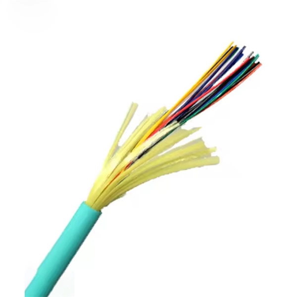
This step-by-step fiber optic cold splicing tutorial makes it easy for beginners and professionals. ✅ One-time splice success – no more trial & error ✅ Mini. Fiber optics is the fastest and one of the safest ways to transmit information online. Fiber optic strands are ultra-lightweight and about as thin as human hair, and yet, they have more than eight times the pulling tension of a copper wire. And because fiber optic cables carry light instead of. This guide explores everything about fiber optic cable splice —from fiber fusion splice basics to how to splice fiber cable step-by-step—covering tools, techniques, and practical tips. This process requires precision, patience, and a deep understanding of the delicate nature of optical fibers. Before any splicing can occur, whether it's mechanical or fusion. Optical fiber Lengjie is used for optical fiber butt optical fiber or optical fiber docking pigtail, which is equivalent to making a joint, (fiber docking pigtail refers to the butt joint between the optical fiber and the core of the pigtail, not the pigtail head mentioned by the former), used for. This guide will walk you through the complete process of fiber optic splicing—covering each step in detail so you can deliver a clean, professional splice every time. Before jumping into the physical steps, it's important to understand the two primary methods of fiber splicing: fusion splicing and.
[PDF]
This post provides you with guidance steps and pictures on how to replace a computer power supply, after the PC power supply unit (PSU) failed. Changing your computer's power supply is a simple enough process that anyone can do, once you know how. This guide will teach you how to replace/change the power supply unit in your computer, step by step. Write down important information from the top or bottom of the power supply, such as the Model Number, Serial Number and specifications (e., voltage and watts). Ensure you are familiar with ESD. "My Computer Will Not Turn On" - Troubleshooting PC Power Supply | Computers and Coffee Thanks For Watching ! Please Like and Subscribe For More Content Like This :). more Audio tracks for some languages were automatically generated. Learn more Thanks For Watching ! Please Like and Subscribe For. Sometimes when you upgrade your PC, you will find that current power supply isn't powerful enough to support your new system. Whatever the reason, doing it right will make the process easier and ensure you have a model that will stand the test of time and deliver uninterrupted power to your computer. Before replacing your PSU, ensure you.
[PDF]

Locating and repairing faulty Dense Wavelength Division Multiplexing (DWDM) network links quickly, and without disrupting existing traffic, is the key to avoiding excessive downtime or SLA penalties. With the commissioning and expansion of dense wavelength division multiplexing equipment in various backbone communications. Backbone network will use dense wavelength division multiplexing equipment as the main bearer channel for 10 Gigabit metropolitan area networks, NGN bearer networks, the. DWDM Network Troubleshooting and Maintenance DWDM (Dense Wavelength Division Multiplexing) systems can experience various complex problems that affect performance. Here are some typical issues: 1. Single-mode optical fiber communication has evolved to improve network reach (distance), innovative modulation formats have increased carrying capacity, and DWDM has. Dense wavelength division multiplexing (DWDM) is a fiber-optic transmission technique that employs light wavelengths to transmit data parallel-by-bit or serial-by-character. This tutorial addresses the importance of scalable DWDM systems in enabling service providers to accommodate consumer demand. 📦 For purchasing, use the RP Photonics Buyer's Guide for wavelength division multiplexing. It provides an expert-curated supplier directory, buyer-focused technical background information, and structured selection criteria to support professional procurement decisions. Wavelength division.
[PDF]

Octal Small Form-factor Pluggable (OSFP) solution that fits into high-density switch and router client ports for optical interconnect links Powered by Greylock and Delphi DSP ASICs, and silicon photonic integrated circuits (PICs) for an optimized co-packaged design with 3D. Octal Small Form-factor Pluggable (OSFP) solution that fits into high-density switch and router client ports for optical interconnect links Powered by Greylock and Delphi DSP ASICs, and silicon photonic integrated circuits (PICs) for an optimized co-packaged design with 3D. In the IP over DWDM Wikipedia page, we see this sentence: (this link) "A true IPoDWDM solution is implemented only when the IP Routers and Switches support ITU-T G. In this way, IP devices can monitor the optical path and implement the transport functionality as FEC (Forward Error Correction). This chapter describes the OTN circuits and procedures to configure the OTN circuits. Feature History GMPLS UNI circuits can now be created for the NCS4K-4H-QDD-P line card. This enhancement optimizes network resources and improves network utilization across packet and optical networks. The most compact multiservice 400G test solution on the market for field applications 400G/200G Ethernet testing capabilities based on IEEE 802. This article introduces the fundamental concept and key characteristics of 400G OSFP Ethernet optical transceivers, and.
[PDF]
Digital Diagnostic Monitoring (DDM) can monitor parameters of the optical module regularly and generate alarms when parameter values exceed thresholds. By using DDM, you can detect issues early to maintain network stability. When you configure the DDM function, follow these notes. Optical Module Monitoring & Troubleshooting 2026 – network-switch. com Digital Diagnostics Monitoring (DDM), also known as Digital Optical Monitoring (DOM) or Diagnostic Monitoring Interface (DMI), is a standardized feature defined by SFF-8472 that allows network devices to monitor real-time optical. Digital Diagnostic Monitoring (DDM), also known as Digital Optical Monitoring (DOM), is a key feature in modern optical transceivers. It can provide the host with real-time data about the module's internal operating conditions, including parameters such as voltage. Digital Diagnostics Monitoring (DDM) is a feature used in optical transceiver modules that enables you to view real-time information about transceivers, such as optical output and input power. For information about which F5 ® transceiver modules support DDM, see F5® Platforms: Accessories. It is an intelligent function that enables network administrators to monitor the transceiver's operational parameters in real time. DDM is not merely a feature; it is an industrialized standard.
[PDF]