This paper puts forward the power method in transmission line protection and the current method in bus protection to achieve full coverage of distribution network protection, and gives the power method.
[PDF]

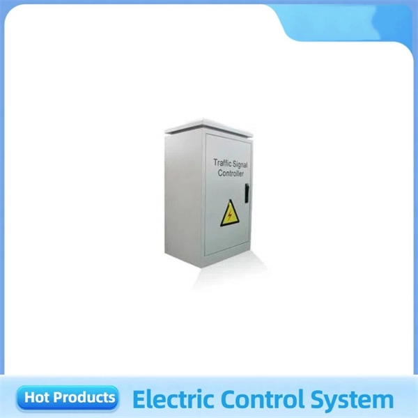
Headquartered in Fort Wayne, Indiana, GMS Distribution distributes and sells its products in the United States and Canada. 30 Amp Portable Power Box GMS's Portable Power Distribution Centers have been designed to be the easiest power box you will ever plug in. GMS is focused on the. Our products boast customizable materials and dimensions, ensuring a tailored experience. With a range of materials to choose from and the ability to adjust sizes to your liking, our offerings are designed to meet your unique needs and preferences. American Distribution Boxes are made of high-density polyethylene for years of dependable use. They are non-corrosive, strong, and lightweight for easy handling. Inlet and outlet elevations are positioned to provide equal distribution and meet most local codes. Twist and lock 4” pipe seals and. It is the high-voltage core unit of the American box type transformer, integrating high-voltage load switches, fuses, etc., with a voltage of mostly 15kV. PREMIUM CONSTRUCTION POWER DISTRIBUTION BOX: Crafted by WESTERN, the 6506TLSX Temp power box features a durable blend material for long-lasting performance in demanding environments. ATEK Distribution supplies professional-grade electrical boxes for residential, commercial, industrial, and government projects nationwide. As a certified SDVOSB with 28+ years of experience, we carry every box type you need — correctly specified, fully documented, and ready to ship. Whether you're.
[PDF]
Home appliances TV sets, VCR, Microwave ovens Office machines Industrial equipment NC machines, Robots, Temperature controllers Photocopiers, Vending machines. Space saving design Wiring can be done with ease (DIN terminal). N.C. contact raw N.O. contact raw COM contact raw Coil terminal raw. N.C. contact raw N.O. contact raw COM contact raw Coil terminal raw. For Cautions for Use, see Relay Technical Information.
[PDF]

In this video, I'll show you how to build a simple and effective short circuit protection circuit using a relay. This DIY project is perfect for anyone looking to protect their electronics from accidental shorts. Last Updated on February 15, 2026 by Swagatam 117 Comments In this post I will try to explain the making of a simple 220 V, 120 V AC mains short circuit breaker using an SCR and a triac combination, (researched and designed by me). The circuit is an electronic version of the normal main circuit. One possible solution to the problem of overcurrent is to use a variable bench power supply with a current limit function. These power supplies allow You to set a current limit, preventing a high current flow when a mistake occurs. This circuit will. Why Publish? How to Make Short Circuit Protection Circuit: Hii friend, Today I am going to make a circuit for Short Circuit protection. This circuit we will make using 12V Relay. How this circuit will Work - when short circuit will occur on the load side then the circuit will be automatically cut o. In this tutorial, we will see how to make a short circuit protection using Relay. Many times accidentally terminals of batteries and other power supplies get short-circuited. Due to this, they get hot and start degrading. In the case of lithium-ion or lithium-polymer batteries, they may catch fire.
[PDF]

This paper presents a set of newly developed modeling, simulation and testing tools aimed at better understanding the design concept and related applications for protective relaying and substation automation solutions for the smart grid. presentation of protection and control relaying. The report will identify methodology behind these practices, present issues raised by the integration of microprocessor relays and the internal logic and external communication configurations, ying. At Keentel Engineering, we specialize in modeling, simulating, and deploying advanced protective relays to ensure the robustness of medium-voltage (MV) and high-voltage (HV) networks. Our engineering services help utilities, OEMs, and renewable developers simulate real-world contingencies and. This Modern Power System Protective Relaying training course has been designed to provide a clear and perfect understanding of power system protection schemes and devices, including protection relays, fuses, circuit breakers, and other protective devices. In modern power systems, nowadays. To ensure that protective relays, circuit breakers, and other protection devices correctly and selectively isolate faults, minimizing damage to equipment and interruptions to customers while maintaining system stability. One-line diagrams and detailed network data (lines, transformers, buses).
[PDF]
of relay protection coordination for a PV power plant connected to the distribution network is presented. In recent years, installation of PV power plants in the distribution network has increased significantly. I.
[PDF]

This video provides a detailed walkthrough of designing and simulating an automatic light control system using Light-Dependent Resistor (LDR) and Triac in Proteus Software. Last updated on 13 August 2025 by Admin-Lavi Leave a Comment This article talks about Light Controlled Switch Circuit using IC LM311 and LDR. It simple and very useful and it feel light change near it. We find this circuit in many place like automatic light, street lamp and security system. Main. ABB's Control Room offering includes a comprehensive range of solutions designed to optimize the operator workspace for critical 24/7 processes across various industries. The project demonstrates how to create a smart lighting system that turns on/off automatically based. more This video. The Intro Screen changes as you play with it. It has a Play Area and a Control Area. A Construction Area creates a building space for components added from a Circuit Component Toolbox. Build and navigate your circuits there. If Voltmeters and Ammeters are out of the toolbox, you can take. Common sense schematics let you name a node "+5V" and know that the simulator will do the right thing automatically, keeping your schematics compact and elegant. This circuit activates or deactivates connected loads, such as LEDs or light bulbs, based on ambient light levels.
[PDF]

Protective relays are special electrical devices used to detect faults in power systems and quickly disconnect faulty parts to prevent damage. These relays sense abnormal conditions like overcurrent, under-voltage, or short circuits and send a signal to circuit breakers to open the. Electromechanical protective relays at a hydroelectric generating plant. The relays are in round glass cases. The rectangular devices are test connection blocks, used for testing and isolation of instrument transformer circuits. In electrical engineering, a protective relay is a relay device. Protective Relay Definition: A protective relay is an automatic device that senses abnormal conditions in electrical circuits and triggers actions to isolate faults. Types of Protective Relays: Protective relays are categorized by their mechanism (electromagnetic, static, mechanical) and function. Combines protection, sensors, control power, and circuit breaker in a single package Typically added to a breaker close circuit to prevent accidental reclosure after a trip. Three fundamental components required for each circuit breaker. It initiates the operation of circuit breakers to isolate the affected section.
[PDF]
Simply put, a relay is an electromechanical device that allows a high power load to be controlled with a low power circuit. The images below show a cross section of a relay very similar to what is on the RELAYpl.
[PDF]

A virtual switch in Hyper-V is a software-based network switch that allows virtual machines to communicate with each other, with the host computer, and with external networks. When you first install the Hyper-V role on Windows Server, you can optionally create a virtual switch at the same time. To learn more about virtual switches, see Hyper-V Virtual Switch. It acts like a physical network switch but exists entirely in software, managing network traffic for your VMs. Hyper-V. This guide walks you through creating and configuring a virtual switch to connect your VMs to external, internal, or private networks. What is a Virtual Switch in Hyper-V? Be sure to check out our previous blog post for a step-by-step guide on installing the Hyper-V Server role on Windows Server. A network switch (also called switching hub, bridging hub, Ethernet switch, and—by the IEEE — MAC bridge) is networking hardware that connects devices on a computer network by using packet switching to receive and forward data to the destination device. A network switch is a multiport network. An Internal Virtual Switch in Hyper-V lets your virtual machines talk only to each other and your host PC. Open the Virtual Switch Manager and create a new Internal switch. Then assign this switch to the network adapter of each guest system. Depending on the type.
[PDF]
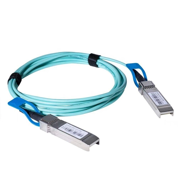
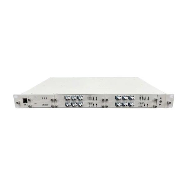
An optical network is a communication system that leverages light to convey information across distances, encoding data into rapid flashes of light instead of relying on electrical voltage changes. At the heart of this ecosystem lies the Optical Transport Network (OTN) — a framework defined by the ITU-T (notably G. 709) that has become the foundation for modern optical communications. This method allows engineers to manage the exponential growth in global data traffic generated by. A passive optical network (PON) is a system commonly used by telecommunications network providers that brings fiber optic cabling and signals all or most of the way to the end user. Depending on where the PON terminates, the system can be described as fiber to the curb, fiber to the building or. An Optical Transport Network (OTN) is a transmission network based on wavelength division multiplexing (WDM) technology. It is a specific type of transmission network that transmits data and manages it using optical signals. OTN is built on a series of protocols, including G. It is designed to provide a high-speed, scalable, and reliable infrastructure for the transmission of data between different network nodes. While there are many subtle differences, a clear distinction between active optical networking and PON topology is PON's use of a.
[PDF]
West Port Middle East specializes in engineering and supplying cable management solutions that meet the precise requirements of electrical contracting projects across the GCC. Unigroup offers a line-up of high-performance cable trays, Trunking and Channel Systems for all your cable routing requirements. Our cable tray systems are engineered for modern infrastructure, ensuring safe, organized, and efficient cable routing across commercial, industrial, and utility. Cable Trays are support systems used in building electrical wiring. These cable support systems are commonly used to support insulated power and communication cables. Cable trays provide a more preferable alternative to electrical conduit systems and open wiring. Cable tray systems are generally. Premium Construction: Made from galvanized steel, stainless steel, or aluminum, these trays resist corrosion and provide high load-bearing capacity in harsh conditions. From residential towers to industrial plants, our extensive portfolio of products and accessories is designed to provide. A form of cable management system used for supporting and arranging electrical cables and wires in commercial, industrial, and residential structures is known as GI Cable Tray, also known as Galvanized Iron Cable Tray.
[PDF]
Dual ring topology is a network configuration that uses two concurrent rings of connections to link devices. This redundant network structure enhances reliability and provides a failover mechanism, ensuring high availability and network uptime. Device Level Ring (DLR) is a Layer 2 protocol that enables redundancy in a ring topology, providing fast network fault detection and reconfiguration for industrial networks. DLR is an EtherNet/IP™ protocol that is defined by the Open DeviceNet® Vendors' Association (ODVA). DLR network includes at. A fiber optic ring network is a physical or logical network topology where devices (usually switches) are connected in a closed-loop using fiber optic cables. Each node is connected to two other nodes, forming a ring-like structure. This design ensures data can travel in both directions. Data travels from node to node, with each node along the way handling every packet. Rings can be unidirectional, with all traffic. This document provides basic background information regarding adding ring redundancy in your wired Ethernet networks. It will explore the N-Tron proprietary protocol N-Ring and how it is a step up from IEEE Spanning Tree and Rapid Spanning Tree Protocol (STP, RSTP). DLR provides a means to detect, manage, and recover from single faults in a ring-based network. A DLR network includes the following types of ring nodes.
[PDF]