
This article provides a detailed technical comparison between fiber optic and copper cables, offering a clear perspective for engineers, network architects, and procurement managers. The core distinction between the two technologies lies in the physics of data. However, the exponential growth in data demand has positioned fiber optic technology as the superior alternative for performance, scalability, and future-readiness., 10G/25G/40G/100G and beyond depending on optics and reach). Copper Ethernet scales too, but practical limits are lower and depend. The two main options are fiber optic cables and copper cables, each with its own advantages and drawbacks. Fiber optic cables are praised for their high performance and scalability, while copper cables remain a cost-effective choice, especially for budget-conscious projects and older systems. Copper wire is more susceptible to interference and has limited data capacity, making optical fiber the preferred choice for modern high-speed. Optical connectivity, utilizing fiber-optic technology, has emerged as the superior choice for modern networking, offering unparalleled performance, reliability, and scalability. For example, a typical 10 Gbps copper Ethernet link (such as Cat 6A) over 100 meters can consume approximately 5 to 8+.
[PDF]

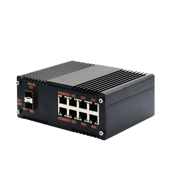
How to Install a Fibre Connector into a Patch Panel (Easy fibre optic connector installation) How to Install a Fibre Connector into a Fibre Optic Patch Panel. How do you install fibre optic connectors?. Connecting a fiber patch panel to a switch is a critical step in setting up a fiber optic network. There are different types of connectors. In today's high-performance networks, fiber optic patch cables are the lifelines that ensure smooth data flow across switches, servers, and routers. Even the most advanced optical transceivers can only perform at their peak when paired with properly installed, clean, and precisely managed fiber. Choose an SFP module based on the fiber optic cabling that will be connected to the network switches. SFP transceiver modules almost always require two fiber optic cable strands. A Fiber Patch cord connects two devices. You plug it into a switch, router, or patch panel. It's ready to use out of the box. A pigtail is for splicing. You fuse it to a. With a railroad switch (patch panel), the train (data) can travel from A to B, C and even more destinations, otherwise it can only go from A to B, or C to D. This article, What Is a Patch Panel Used for?, has explained it thoroughly.
[PDF]

This article will compare waterproof connectors and non-waterproof connectors, highlighting their key differences, advantages, and best use cases in FTTH deployments. 🔍 What Are Waterproof Connectors?. In modern fiber optic deployments, one of the biggest challenges is ensuring stable and long-term connectivity in harsh outdoor environments. The comparison is typically triggered during outdoor deployments, edge network extensions, or hybrid indoor–outdoor transitions where connectors may be exposed. This is where Ruggedized Fiber Optic Connectors come in. Whether you are connecting a Remote Radio Unit (RRU) for Ericsson, Nokia, or Huawei, or setting up a harsh-environment sensing network, choosing the right waterproof interface is critical to preventing signal loss and network downtime. In. In today's fast-paced digital world, the choice of fiber optic connectors can significantly impact performance, reliability, and longevity of networking solutions. Among the varieties available on the market, waterproof fiber optic connectors have emerged as a superior option for many applications. In this blog, we will focus on comparing the performance of Mini LC.
[PDF]

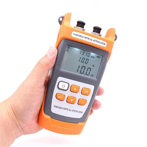
The document discusses optical detectors used in fiber optic communications systems. It describes the functioning of PIN photodetectors and avalanche photodetectors (APDs). Their performance. An optital detector is a device that converts light signals into electrical signals, which can then be amplified and processed. Such detectors are one of the most important components of an optical fiber communcation system and dictate the performance of a fiber optic communication link. PIN Photodiode A PIN photodiode is a widely. Detectors perform the opposite function of light emitters. The most common detector is the semiconductor photodiode, which produces current in response to. It explains how these devices use optical fibers to measure quantities like temperature, mechanical strain, pressure, and vibrations by detecting changes in light propagating through the fiber. A central focus is on sensors based on fiber Bragg gratings, where the Bragg wavelength is sensitive to. Optical Power Meters: These devices measure the power of optical signals in fiber optic cables. This information helps in maintaining signal integrity and quality across the.
[PDF]
Under the TIA/EIA-598-C standard, the universal 12-color sequence is: 1-Blue, 2-Orange, 3-Green, 4-Brown, 5-Slate (Gray), 6-White, 7-Red, 8-Black, 9-Yellow, 10-Violet, 11-Rose, and 12-Aqua. This sequence repeats for cables with more than 12 fibers. Table 151-13 uses the worst case S0 and ZDW given in Table 151-14, and calculates the worst case positive and negative dispersion using the worst case TX wavelengths given in Table 151-7 and footnote (b), and the worst case fiber length (operating distance). 3 has analyzed. The two fiber parameters that have the greatest effect in limiting digital transmission over optical waveguides are attenuation and pulse spreading. In single-mode fibers, pulse spreading is caused by chromatic dispersion. Attenuation attracted most of the attention in the early years of. *Values for cabled fibre, local attenuation discontinuity ≤0. 1dBNote: Due to OTDR measurement uncertainty B3 International cannot guarantee attenuation values at fibres shorter than 1000m. Parameters are subject to change without notice. General Symmetric cable pairs Land coaxial cable pairs Submarine cables Free space optical systems G. 649 Optical fibre cables G. @1310nm (typical/max. The tutorial has the following parts: Chromatic dispersion is the phenomenon that the phase velocity and the group velocity of light propagating in a fiber depend on the optical frequency. It is relevant for many applications.
[PDF]
Strip the cable the required length, minimum 0. 5 meter or more, to establish easy and safe installation with enough buffer size. Pass the stripped cable into the upper side of the splice tray. Fix the cable strength member (3) on part (2) and stabilize with cable fixing part. To establish easy and safe installation put the box where it will be installed and measure the required length of the cable. 5 meter or more, to. Lockable Cable inputs: 2x 12mm - 16x Space for 1x16 SC splitter or 1x32 LC splitter 1. Cable fixing Instert the stripped cable through the cable entry port and fasten the FRP element(s) to the block. The outher coating should be fasten useing the steel hops. Do not fasten too. Stripping and preparing fibre optic cables for termination is a critical step in the installation and maintenance of fibre optic networks. Firstly, it is important to consider that when stripping multi-layer cables for connectorization, each layer must usually be stripped individually, as they all usually need to be stripped to different lengths. Cutting and stripping the cable jacket can be done with a special fiber stripper or a properly set wire stripper as long as it does. Whether it is indoor or outdoor fiber-optic (FO) cable, using a step-by-step approach reduces the chance of fiber damage while ensuring the performance of fibers. In our continuing discussion of installing FO cables, let's use a step-by-step approach in detailing how to strip and clean indoor and.
[PDF]

Identify and compare relevant B2B manufacturers, suppliers and retailers. Identify and compare relevant B2B manufacturers, suppliers and retailers. Identify and compare relevant B2B manufacturers, suppliers and retailers Max. Brolis Sensor Technology specializes in advanced photonic sensor technologies, including the development of integrated optical sensors for healthcare and industrial applications. Their innovative sensors utilize. Fiber Optic Devices Ltd. (FOD), an employee owned company, is a complete fiber optic technology company offering a variety of products and services to the OEM and End-user markets. Founded in 1991, FOD is a recognized leader in partnerships in the design and manufacturing of Fiber Optic Components. Also, please take a look at the list of 38 optical sensor manufacturers and their company rankings. Here are the top-ranked optical sensor companies as of May, 2026: 1. WIN SOURCE ELECTRONICS, 2. Vishay Intertechnology, Inc. The Workshop of Photonics (WOP) specializes in femtosecond laser micromachining, providing ultra-high precision services for various materials, including glass and ceramics. Their innovative approach enhances productivity and provides critical data for improving nutrition and.
[PDF]

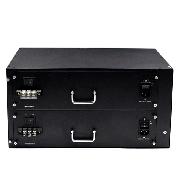
An Optical Distribution Frame (ODF) is a dedicated unit designed to organize, terminate, and interconnect fiber optic cables. It brings together fiber splicing, patching, and cable routing in a single structure, while shielding sensitive connectors and splices from mechanical. In the complex architecture of fiber optic networks, the Optical Distribution Frame (ODF) serves as the linchpin for organizing, protecting, and distributing optical signals. Whether in data centers, telecom central offices, or enterprise network rooms, ODFs enable efficient fiber management. This complete guide explores everything you need to know about ODFs — from their structure, types, and key components, to installation best practices and modern design trends. They provide efficient fiber optic management, connectivity, and protection. ODF, also known as optical distribution frame or fiber optic patch panel, is a critical device used in optical communication for managing and distributing optical fibers. As data centers, enterprises, telecom operators, and smart-building infrastructures deploy increasingly dense fiber links, ODFs provide the structured. An ODF is a central hub in fiber optic networks, crucial for managing and organizing the variety of fiber-optic cables and connections entering a facility such as a telco central office (CO).
[PDF]
As a critical component in high-speed networks, fiber optic patch cords require micron-level precision. This guide unveils the complete production workflow compliant with **IEC 61754** and **Telcordia GR-326-CORE** standards, featuring proprietary quality control. If you've ever troubleshot a fiber optic network only to find that a microscopic dust particle caused the entire system failure, you understand why IPC-8497-1 exists. This standard represents the industry's collective wisdom on how to properly clean and assess contamination in optical assemblies. For harsh environments or other data center and IT networking applications where there is a greater risk of damage to your fiber optic network, armored fiber optic cables deliver the protection you require. Built with a steel-armored layer that provides extra crush and rodent resistance, these. Welcome to be our agent! Fiber optic patch cords, also known as fiber jumpers, are essential components in high-speed data transmission networks. Their performance directly impacts signal quality, insertion loss (IL), and return loss (RL). At ZION Communication, we design and manufacture a full range of fiber patch cords for: This guide will help you quickly understand the main types of. Ensuring the performance and reliability of fiber optic patch cords is fundamental to optical network integrity. 6-Step Manufacturing.
[PDF]

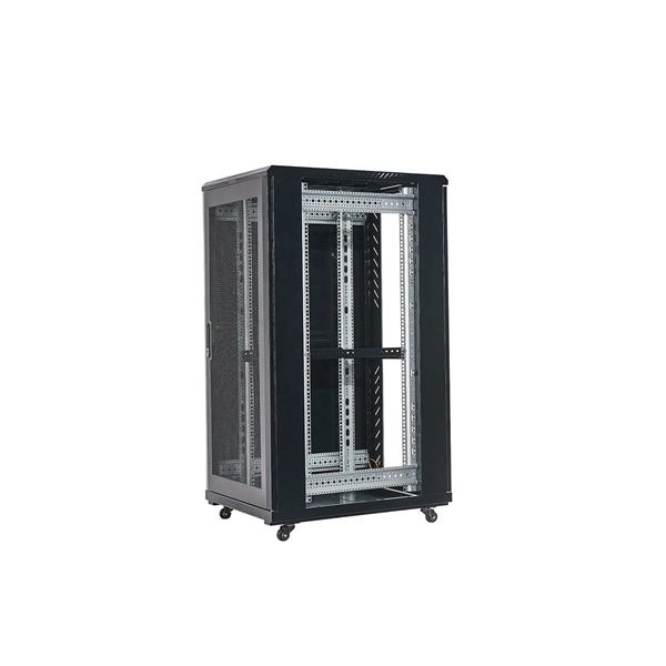
Here's a step-by-step guide to help you properly arrange fiber optic patch panels in a data center environment. Before installation, assess your network's current and future needs:. Effectively arranging optical fiber optic patch cords in a cabinet is a critical aspect of maintaining a streamlined and organized network infrastructure. Proper arrangement not only enhances the overall aesthetics of the cabinet but also plays a crucial role in preventing signal interference and. As networks move to higher speeds and higher density, choosing the right fiber optic patch cords becomes critical to the reliability of your system. At ZION Communication, we design and manufacture a full range of fiber patch cords for: This guide will help you quickly understand the main types of. You need fiber patch cord installation and maintenance for a strong network. If you do not handle them well, connectors can get misaligned. Rough handling can also cause problems. Fiber optic patch cords, also known as fiber optic patch cables or fiber jumpers, are indispensable components in modern optical networks. They act as the critical link for interconnecting devices like optical switches, servers, and distribution frames. Understanding the various technical. You need fiber optic cables. But the options are overwhelming. One customer ordered 50 LC-SC patch cords. They were all the wrong polish type. The network failed during testing. This happens more than you think.
[PDF]

l LongXing GPJ83-D18 fiber optic splice closures are specially designed to protect joints of optic cable. l The scope of application is: aerial, wall-mounting, and pole-mounting. The ambient temperature ranges from –40℃ to +65℃. l The closure adopts mechanical and heat shrinkable. The GPJ83-D18 Dome Fiber Optic Splice Closure are closures which accommodate the joint part of the cable, that can be used in aerial-hanger, wall-mounting or pole-mounting. This kind of dome splice closure includes three types, namely GPJ83-D18-A, GPJ83-D18-B, GPJ83-D18-C, GPJ83-D18-D, which. –High strength dust proof and waterproof function, suitable for aerial installation –The box body adopt push pull mechanical locking mode, with design of buckle type, easy to operate, reusable and reliable –Adapter and splitter can be assembled, 18pcs adapter can be equipped UV, 2pcs micro. Up-down bisection GPJ-M is an arc, horizontal type. Innovative insert plates and fixing bolts are used to fix and seal FOSC, and its installation is quite simple. The FOSC is suitable for protecting fiber cable splices in straight-through and branching applications. Speed Optic' s closures can be divided into two series: horizontal type and dome type. As for dome type, according to the sealing ways, including shrinkable. Dome GPJ-O is a vertical type. GPJ-O is provided with 4 fiber cable inlet/outlet ports and sealing is achieved by tightening nut after inserting fiber cable.
[PDF]
Connecting a fiber patch cord involves carefully inserting it into the appropriate adapter after ensuring the connectors are clean. The process may differ slightly depending on the type of connector. The core process involves two main stages: preparation and insertion. Planning helps you pick the right cord for your network. Be gentle when you handle the cord. Fibre patch cords last longer and are tougher than copper cables. They also protect better from interference. Look at the table below to compare:. Connecting a fiber optic patch panel may seem daunting at first, but if you follow the right steps, it's actually quite simple – and can even be done in just a few minutes. Preparation: Before. Fiber Optic Transceivers: For converting signals between optical and electrical form. Cleaver: For precisely cutting the fibers. Safety Equipment: Gloves. In today's high-performance networks, fiber optic patch cables are the lifelines that ensure smooth data flow across switches, servers, and routers. Even the most advanced optical transceivers can only perform at their peak when paired with properly installed, clean, and precisely managed fiber. Correct patch-cord installation is essential for maintaining low insertion loss, stable return loss, and long-term reliability in both indoor and outdoor fiber networks. Proper handling, routing, cleaning, bend-radius management, and connector alignment ensure that the optical link meets design.
[PDF]
Single-mode optical splitters are optimized for single-mode optical fiber, while multimode optical splitters are tailored for use with multimode optical fiber. An Optical Splitter, also known as a beam splitter, is a passive optical device that divides a single input optical signal into two or more output signals. Conversely, it can also combine multiple signals into one. Its primary role is in Passive Optical Networks (PON), which are the foundation of. This guide demystifies fiber optic splitters, explaining their design, operating principles, types, key specifications, and real-world applications. It can distribute the optical energy transmitted through a single fiber to two or more fibers in a predetermined ratio or combine the optical energy from multiple fibers into one fiber. “Passive” means it needs no. You use optical couplers and splitters to split or join signals in fiber networks. For example, optical splitters send light to many output ports. This lets you connect more users to one network terminal. There are different types of fiber optic splitters available, with two of the most common being Fused Biconical Tapered (FBT) splitters and Planar Lightwave.
[PDF]