It is currently used in modern three-CCD cameras. An optically similar system is used in reverse as a beam-combiner in three- LCD projectors, in which light from three separate monochrome LCD displays is combined into a single full-color image for projection.OverviewA beam splitter or beamsplitter is an that splits a beam of into a transmitted and a reflected beam. It is a crucial part of many optical experimental and measurement systems, such as. In its most common form, a cube, a beam splitter is made from two triangular glass which are glued together at their base using polyester,, or urethane-based adhesives. (Before these synthetic,. Beam splitters are sometimes used to recombine beams of light, as in a. In this case there are two incoming beams, and potentially two outgoing beams. But the amplitudes.
[PDF]

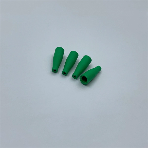
Mainly 9steps: Step 1: cut cable with cutting machines in lengths Step 2: put the connector spare parts on the cable Step 3: Strip cable jacket, coating till bare fiber, and make all parts in ready Step 4: Insert fiber into ferrule, glue dispenser and heat oven Step 5:. Mainly 9steps: Step 1: cut cable with cutting machines in lengths Step 2: put the connector spare parts on the cable Step 3: Strip cable jacket, coating till bare fiber, and make all parts in ready Step 4: Insert fiber into ferrule, glue dispenser and heat oven Step 5:. Learn how to make a fiber optic patch cord step by step, from preparation to testing, for reliable high-performance connections. Most guides on making fiber optic patch cord 1 s feel incomplete. They often focus on the final assembly steps, leaving the foundational stages a mystery. From cable cutting to connector assembly and testing, you will gain valuable insights into the production of. Fiber optic patch cords and Pigtails are very important passive fiber optic components in fiber optic networks. Use the fiber optic cleaver to cut the. This document describes the installation and use of the mode-conditioning patch cords listed in Table 1. A mode-conditioning patch cord is shown in Figure 1 IEEE 802. 3z-compliant optical fiber assembly consisting of a single-mode fiber permanently coupled off-center to a 62. 5-micron multimode.
[PDF]
This guide covers the critical steps, from selecting the right electrical cable tray and performing accurate cable fill calculations to managing a safe cable pull through and ensuring all bonding and grounding requirements are met. But before you lay the first tray or clamp down a single cable, you need a solid plan. This guide breaks down the process step by step. Plan the Route Before You Drill No installation should start without a plan. For licensed electricians, mastering these principles is essential. Cable tray installation implies the construction of an electric road that will be safe. In order to get it right, installers are supposed to adhere to a plan that ensures that wires are kept cool and the building is stable. The beginning of success is to review the Bill of Quantities (BOQ) so that. Cable tray systems provide a safe, organized, and flexible method for supporting insulated conductors and cables in commercial and industrial electrical installations. When properly selected and installed, cable trays simplify routing, improve accessibility, and support future expansion while. Proper installation of cables in trays is critical for maintaining an efficient and safe electrical system. This process is integral to determining the optimal arrangement and configuration of cable trays, which are essential for routing and supporting electrical cables within buildings and.
[PDF]

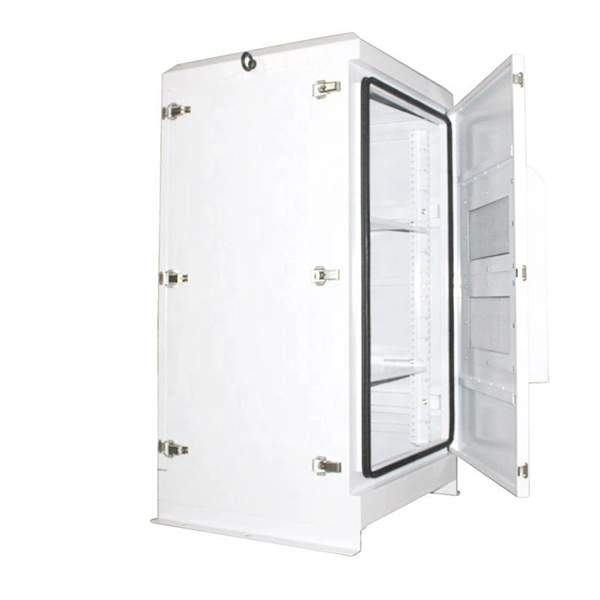
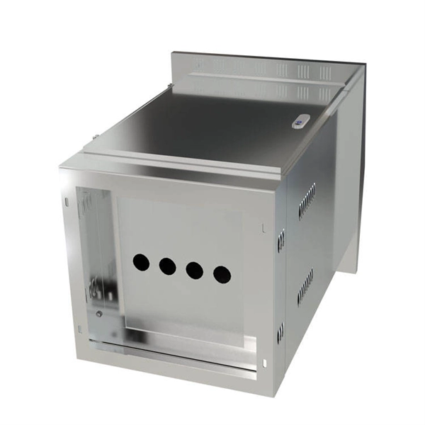
Within data centers, optical distribution boxes manage fiber connections between servers, switches, and storage devices. They enable high-density fiber management, reducing cable clutter and improving airflow. This use-case enhances data transfer speeds and system uptime. They protect delicate fiber cables from environmental factors like moisture, dust, and physical damage. These boxes are used in various settings, including outdoor street cabinets. Optical fiber distribution box (often referred to as optical fiber distribution box or ODF box) plays a crucial role in optical fiber networks, and its advantages are mainly reflected in the following aspects: First, efficient fiber management Modular design: The optical fiber distribution box. These boxes simplify network expansion and reduce installation complexity by combining fiber distribution and signal splitting functions in one enclosure. FDB is used for the purpose of distributing and terminal connection to numerous types of optical fiber systems. They are commonly used by FTTH clients wiring equipment, in order to provide protective connections. The box is compact, light and is widely used for end termination of villas and. An Optical Distribution Frame (ODF) is a specialized enclosure designed to manage, connect, protect, and distribute fiber optic cables in telecom and data networks. It acts as a central point for terminating, splicing, and distributing these cables, providing necessary protection and.
[PDF]

Single fiber modules (BiDi) use one fiber for both transmitting and receiving data. This saves space and money. They are easier to set up and give steady communication. They use a thin fiber. Pioneer LX305 only has 1 optical input, can I add another with some kind of splitter? I love my new receiver but I need a second optical input and I'm wondering what my options are in this regard. Can anyone help? Thanks in advance. Edit: Everyone is going to ask this question, so here are my. The single-mode optical fiber is designed and engineered to carry one single light mode in a minimal core diameter. It is specified as the best for especially long-distance applications than multimode fiber. Due to its. The optical module serves as a crucial component in optical fiber communication systems, operating at the physical layer, which is the lowest layer in the OSI model. Its primary function is to achieve optoelectronic conversion by converting electrical signals into optical signals and vice versa. An. There are single-fiber and dual-fiber optical transceivers. How do we choose, and what are their differences and advantages? Let's learn about this! What is a Single-Fiber (BiDi) Transceiver? Single fiber module also called BiDi transceiver or WDM module.
[PDF]

Just connect an Ethernet cable from the modem or ONT to the closest Ethernet jack, and then do the same with the router in the room where you want it (if an Ethernet jack is available, that is). The network switch connecting all your Ethernet cables should automatically pair. The process to connect fiber optic cable to router requires careful attention to detail, but I'll walk you through every critical step with the precision and clarity you deserve. This comprehensive guide combines industry standards with field-tested practices to ensure you achieve a rock-solid. Setting up an internet connection involves a complex journey, starting at the data centers where internet services are routed, and ending at subscribers' home routers. This process involves multiple fiber optic components, accessories, and networking equipment to ensure fast, reliable, and secure. However, setting up a fiber optic connection to your router can seem daunting if you're unfamiliar with the process. In this guide, we'll walk you through how to connect a fiber optic cable to a router safely and efficiently. The fiber. The primary advantage of using a wireless solution for connecting your upstairs floor to your network is that it may not require drilling holes. The simplest way to extend a Wi-Fi network is via a Wi-Fi repeater (range extender). Check compatibility: Before you begin, make sure your router supports fiber optic connection.
[PDF]
To connect a router to a switch, simply plug an Ethernet cable into one of the router's LAN ports and connect the other end to any port on the switch. This creates a seamless network where multiple devices can share the internet connection and communicate efficiently. What is the best method to use when connecting a router to your core switch? Should I put the switch port in a vlan where the IP of the router interface is or should the port not be a switchport and give it an IP? I know both methods will work but I want to know what is the better method to use. Here is what you can do by connecting a switch to your router: Increase the available number of Ethernet ports and improve network efficiency by eliminating Wi-Fi congestion. Optimize how you set up your networking infrastructure. This configuration is great when you have lots of devices that need. While a wireless router is fine for most users, a network switch provides additional ethernet ports for wired devices. Whether you are setting up a small home network or a large-scale enterprise network, understanding how to connect these essential networking devices is crucial. Switches are responsible for transferring data within a LAN, while routers are responsible for transferring data between different networks. In this blog, we'll provide a step-by-step guide to help you achieve it.
[PDF]

How to Install a Fibre Connector into a Patch Panel (Easy fibre optic connector installation) How to Install a Fibre Connector into a Fibre Optic Patch Panel. How do you install fibre optic connectors?. Connecting a fiber patch panel to a switch is a critical step in setting up a fiber optic network. There are different types of connectors. In today's high-performance networks, fiber optic patch cables are the lifelines that ensure smooth data flow across switches, servers, and routers. Even the most advanced optical transceivers can only perform at their peak when paired with properly installed, clean, and precisely managed fiber. Choose an SFP module based on the fiber optic cabling that will be connected to the network switches. SFP transceiver modules almost always require two fiber optic cable strands. A Fiber Patch cord connects two devices. You plug it into a switch, router, or patch panel. It's ready to use out of the box. A pigtail is for splicing. You fuse it to a. With a railroad switch (patch panel), the train (data) can travel from A to B, C and even more destinations, otherwise it can only go from A to B, or C to D. This article, What Is a Patch Panel Used for?, has explained it thoroughly.
[PDF]