
These systems work together to achieve the correct balance of temperature, which affects glass viscosity, and draw “tension. ” Other subsystems are instrumental in avoiding vibration and in assuring the bare fiber is not exposed to dust, moisture, and other contaminants. Legal status (The legal status is an assumption and is not a legal conclusion. Google has not performed a legal analysis and makes no representation as to the accuracy of the status listed. ) Current Assignee (The listed assignees may be inaccurate. Two primary processes exist: cold fill and hot fill. Understanding their differences helps manufacturers make informed decisions. Cold Fill: Room Temperature. Optical fibres in a cable are normally protected in one of two ways, either being tight buffered or contained in loose tubes. Fiber is drawn vertically. Step 1: Preparing the Raw Material – Silica The first stage in making a fiber optic cable begins with the raw material: silica (silicon dioxide). Silica is chosen because of its purity and ability to transmit light efficiently with very little loss. The silica is refined and shaped into large. An annealing furnace design has been proposed to lower the attenuation of optical fiber by lowering its fictive temperature during the fiber draw process. The fictive temperature of Germania-doped single mode o fiber lies in the range of 1150~1300 C and this can be tailored by controlling the.
[PDF]
Fiber testing is the process of verifying the performance of optical fiber cabling. This process includes a range of tests and measurements such as insertion loss, optical return loss, and fiber length. It encompass.
[PDF]

As pluggable I/O data rates increase, the need to efectively limit EMI emissions and heat generated by fiber optic transceivers simultaneously arises. Typically this is done through an EMI containment vehicle such as a sheet metal cage or die cast housing. Legal status (The legal status is an assumption and is not a legal conclusion. Google has not performed a legal analysis and makes no representation as to the accuracy of the status listed. ) Current Assignee (The listed assignees may be inaccurate. In this guide, we will cover everything from what causes heat, to monitoring your SFP module temperatures in real. The developments introduced in the optical communication systems have been focused in 3 main objectives: increase of the propagation distance, increase of the transmission capacity (bitrate) and reduction of the deployment and operation costs. The achievement of these objectives was only possible. With the growing global deployment of Fiber-to-the-Home (FTTH) networks driven by the demand for ensuring high-capacity broadband services, mobile network operators (MNOs) face challenges of excessive energy consumption (EC) of wired optical access networks (OANs). This article will focus on I/O. Fiber optical transceiver is one of the key components of the fiber optic communication systems. The fiber optical transceiver modules convert electrical signal and optical signal to each other to exchange information.
[PDF]
This comprehensive handbook will offer a completely updated and revised guide to lasers and laser systems, including the full range of their technical applications. Laser diodes offer high power for their size and produce electrical-power-efficient laser radiation. They consist of a p-n semiconductor junction, with a forward bias voltage applied to trigger a current through the junction. This induces population inversion (of electrons in the excited state) in. A diode laser, also known as a laser diode or semiconductor laser, is a compact electronic device that converts electrical energy directly into coherent light through the process of stimulated emission. The term “laser” is actually an acronym, standing for Light Amplification by Stimulated Emission of Radiation. The first volume outlines the fundamental components of lasers, their properties and working principles, with brand new chapters in. From telecommunications and data storage to medical surgery and 3D sensing, a laser diode is essential for barcode scanners, printers, and industrial cutting. The laser diode is an unsung hero of modern technology. Operational Mechanism: Laser diodes create light through stimulated emission within an optical cavity, with the light's properties influenced by the semiconductor.
[PDF]

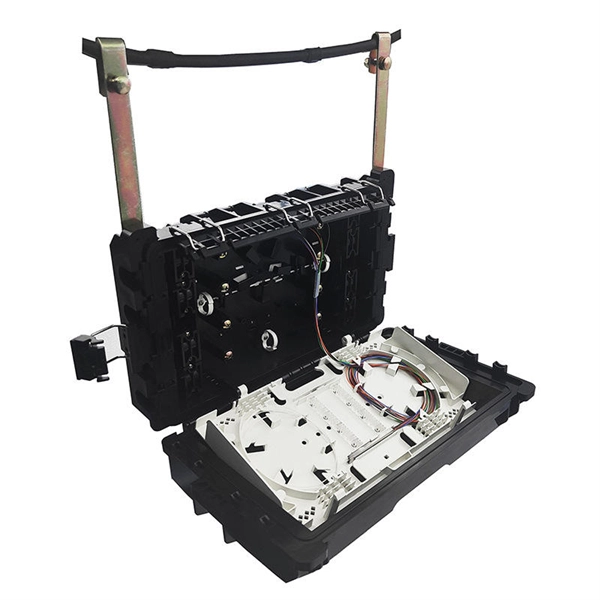
Learn how to install a fiber optic termination box step-by-step for FTTH projects. Covers mounting, splicing, routing, labeling, and testing for indoor/outdoor use. Installing a fiber optic termination box is one of those jobs that looks simple on paper. A fiber termination box is the standard instrument used in fiber optic networks to connect, secure, and protect optical fibers at the terminating point. Proper installation and maintenance of FTBs are essential to ensure the reliability and performance of the network infrastructure. Before. FTTP or fiber To The Premises applications have reinforced the importance of reliable and stable fiber optic terminations. Good quality fiber laying and termination systems help achieve minimal back reflection and low signal loss. They also feature resistance to moisture, impact, chemical exposure. New pole mount bracket YK-SX, made by Jera line, to attach and reattach the fiber optic termination boxes, during aerial fiber deployment. No more time losses on reattaching the termination box from the pole. It serves as a critical junction point within a network, providing a centralized and secure. A Fiber Termination Box, also known as a Fiber Distribution Box, is a crucial component in fiber optic networks. FTBs play a vital role in ensuring the.
[PDF]
This video shows real on-site footage of electrical installation, demonstrating safe and standardized wiring methods used by professionals. more Learn how to wire a distribution box step by step!. Temporary power systems are essential for construction projects, yet they often introduce serious safety risks. Loose wiring, exposed connectors, and unstable electrical connections can cause shocks, equipment failures, or costly downtime. This article examines how modern portable power cabinet. work requires electrical power for many purposes. However, exposure to weather, frequent relocation, rough use and other condi-tions not normally encountered with conventional wiring systems necessitate special consideration not require in other applications or in completed structures. The. Metal raceways, cable armor, and other metal enclosures for conductors shall be metallically joined together into a continuous electric conductor and shall be so connected to all boxes, fittings, and cabinets as to provide effective electrical continuity. The requirements of Article 590 apply to temporary power and lighting installations and removals, including. Learn what OSHA requires for temporary wiring on construction sites, from grounding and GFCI protection to overhead clearances and employer liability. Temporary wiring on construction sites must comply with the electrical safety standards in 29 CFR 1926, Subpart K. These federal rules, enforced by.
[PDF]

In practice, there are two main ways to terminate fiber optic cable: using a connector to join two fibers to create a temporary, removable joint, or using splicing technology to permanently join two bare fibers directly. Either. Terminating fiber optic cables essentially means putting connectors on fiber optic cable so that you can connect the cable to various devices or network components. Think of it as the equivalent of connecting the dots in a complex puzzle; without proper termination, the whole system can break down. Fiber optic networks are the backbone of modern communication systems, enabling high-speed data transfer and reliable connectivity. When deploying fiber optic cabling, one of the most critical decisions is how to terminate the fiber—either by splicing or using connectors. The process of fiber optic cable termination is the essential act of connecting fiber optic cables to devices, patch panels, or other cables to enable. This Applications Engineering Note explains how different optical fiber termination methods impact the optical performance of telecommunications systems. Optical fiber cabling systems support various communications technologies that use digital as well as analog signaling. This involves either installing a connector or creating a splice to establish a reliable connection point for the optical signal.
[PDF]
This article covers various types of protective relays, such as overcurrent, directional, and differential relays, highlighting their operating characteristics and applications in electrical systems. Different Types of Protective Relays What is a Protective Relay?. Protective relays and devices have been developed over 100 years ago to provide “lastline”of defense for the electrical systems. They are intended to quickly identify a fault and isolate it so the balance of the system continue to run under normal conditions. The selection and applications of. Protective Relay Definition: A protective relay is an automatic device that senses abnormal conditions in electrical circuits and triggers actions to isolate faults. Types of Protective Relays: Protective relays are categorized by their mechanism (electromagnetic, static, mechanical) and function. A protective relay is an intelligent electrical device designed to detect faults in power systems and initiate corrective actions such as tripping a circuit breaker. : 4 The first protective relays were electromagnetic devices, relying on coils operating on moving parts to provide detection of abnormal operating conditions such as. Relion protection and control relays for several application reduce complexity.
[PDF]
