
It is a technique that uses controlled heat to permanently fuse two optical fiber ends together. Unlike mechanical splicing, which relies on alignment sleeves and index-matching gel, this thermal approach creates a continuous glass path between fibers. Optical fiber transmission has the advantages of wide transmission frequency, large communication capacity, low loss, no electromagnetic interference, small diameter of optical cable, light weight, rich source of raw materials, etc., so it is becoming a new transmission medium. When light is. Common splicing methods include optical fiber cold splicing and optical cable hot fusion splicing. Advantages and disadvantages of fiber optic cold splicing Fiber cold splicing refers to using special tools to mechanically connect two optical fibers. Its advantages include: Simple operation and. This is part 6 of a tutorial on passive fiber optics from Dr. The tutorial has the following parts: Optical fibers can be joined together, such that light is efficiently transferred from one fiber to another. There are various possibilities: Mechanical splicing means that two fiber ends. This guide reveals the secrets to fusion splicing with little fluff—just proven, straightforward techniques refined from years of work in the field. The result is a joint that closely matches the.
[PDF]
This comprehensive guide will delve into the most effective practices, key considerations, and strategic approaches for designing and implementing an efficient cabling system within a data center environment. At the core of data center connectivity are fiber optic cables, which are thin strands of plastic that transmit data using light signals or wavelengths, offering unparalleled speed and efficiency. The data superhighway paved by fiber optics forms the backbone of modern data centers, ensuring rapid. An end-to-end cabling system is an ideal solution for data centers especially when time for traditional cable installation and termination is limited. Explore advanced configurations, testing protocols, and industry best practices. As the demand for data surges, these switches become more vital in sustaining networks that are efficient, scalable, and. As data centers continue to grow in complexity and scale, efficient fiber optic cabling is essential for maintaining high performance, reliability, and scalability. Proper planning and implementation of cabling infrastructure can significantly reduce downtime, improve airflow, and ensure. center hardware layout design. This map should include the cabinet placements, patch panels, hardware, port-counts, trunking locations and power access connection points. Future plans for change will be discussed, as well as the bandwidth required. infrastructure design. The design's intent is to.
[PDF]
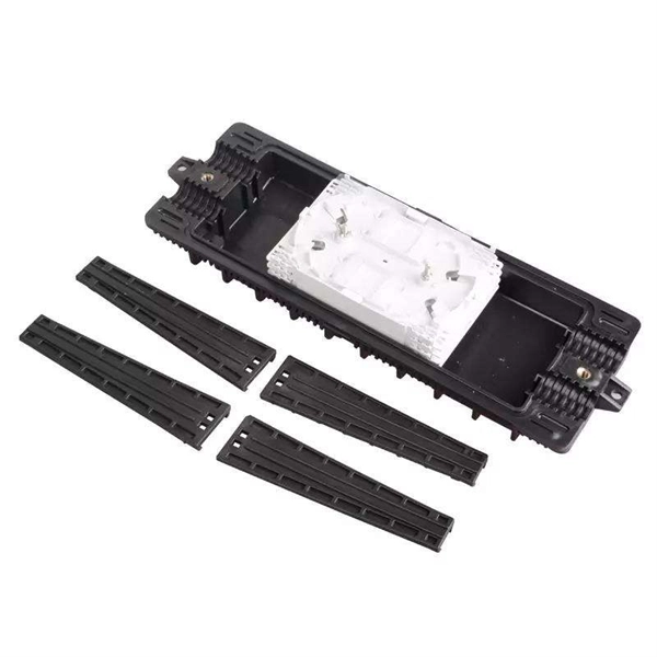
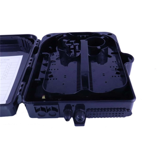
Plan your outdoor fiber installation carefully by surveying the site, choosing the right cable type, and following FOA and OSP standards to ensure reliability. Select the best installation method—direct burial, aerial, conduit, or underwater—based on your environment and. Underground cables are pulled in conduit that is buried underground, usually 1-1. 2 meters (3-4 feet) deep to reduce the likelihood of accidentally being dug up. In extreme cold climates, cables may need to be buried at greater depths where there temperatures are colder and frost penetrates to. We are Jera line, a factory that produces cable infrastructure products. FODB-8 is installed with adapters, splitters, drop cable patchcords, pole bandings, and fiber cable slack storage. Use. pport cables and splice enclosures. Cost of rack Wire Splice B x (200 (50' Mi As ve 1'-0" wide (min) concrete apron. rons shall be sloped away from box. Cost of apron o d oun. FTTP or fiber To The Premises applications have reinforced the importance of reliable and stable fiber optic terminations. Good quality fiber laying and termination systems help achieve minimal back reflection and low signal loss. They also feature resistance to moisture, impact, chemical exposure. Fiber optic cable may be installed indoors or outdoors using several different installation processes. Outdoor cable may be direct buried, pulled or blown into conduit or innerduct, or installed aerially between poles.
[PDF]

In this guide, we break down the two core stages of optical fiber manufacturing: preform production (shaping the precursor material) and fiber drawing (transforming the preform into thin, usable fiber). Optical fiber preforms are the starting point behind every kilometer of fiber optic cable. Though rarely seen by end users, these cylindrical glass rods serve as the base material from which high-speed optical fibers are drawn. As global communication relies more than ever on fiber networks—from. 📦 For purchasing, use the RP Photonics Buyer's Guide for fiber preforms. It provides an expert-curated supplier directory, buyer-focused technical background information, and structured selection criteria to support professional procurement decisions. During the fiber drawing process, the preform is heated and drawn into a. The production of optical fiber is a precision-driven process that transforms raw materials like silicon tetrachloride into ultra-thin, high-performance fibers capable of transmitting terabits of data over thousands of kilometers. Who invented optical fiber and when? Corning scientists Dr. Peter Schultz, and Dr.
[PDF]
In this video, I have explained and verified the Telnet & SSH configuration on an H3C Switch (Model 6520). As shown in Figure 1, the AC is a Telnet server. Make sure the network connections are available. Click the System View tab at the bottom of the page. From the navigation pane, select System > Resource. On the IPv4. To create a user on an H3C switch, you can perform this operation through a web interface or SSH. Follow the commands below to create a user: Specify the user's access level. The same CLI commands and configuration steps can also be applied to other H3C switch models. You will be in the AUX user interface if you log in through this port. 2 User Interface Number Two kinds of user interface index exist: absolute user interface index and relative user interface index. H3C S5100-SI/EI Series Ethernet Switches Chapter 1 Logging In to an Ethernet Switch 2) A relative user interface index can be obtained by appending a number to the identifier of a user interface type. The relative user interface indexes are as follows: z z. Add the specified port to the current VLAN Configure the link type of the port as Trunk type Allow the specified VLAN to pass through the current Trunk port Set the default VLAN for the trunk port Configure the link type of the port as Hybrid View the VLANs that exist on the current switch View the.
[PDF]

Mechanical Optical Switches: Switching times typically range from 1-10ms, suitable for long-distance transmission scenarios where latency is not critical (such as backbone network protection switching). Solid-State Optical Switches: Based on thermooptic or electrooptic effects, response. We lead the industry in optical switch technology, delivering the lowest insertion loss (0. 2 dB), fastest switching speed (10 ns), broadest wavelength range (300–2400 nm), widest fiber compatibility, highest optical power handling (50 W), and space-qualified reliability. Backed by over 25 years of. Use this optical switches buying guide to compare major types, define selection criteria, and find suppliers: Professional purchasing of high-value photonics products is a substantial responsibility, where a structured decision-making process is essential. RP Photonics offers a lot of help: Get. This document is a troubleshooting and selection guide for common optical switch failures, compiled based on over 500 field cases. These switches are built on proven, reliable optomechanical technology that has seen more than 30 years of successful operation. Each. The POLATIS ® Series 7000 384x384 all-optical circuit switch is designed to meet the most demanding applications with exceptionally low optical loss, compact size, and fast switching speeds. With support for Software-Defined Networks (SDNs) via embedded NETCONF and RESTCONF control interfaces, the.
[PDF]
When working with laser light, a plate or cube beamsplitter offers the best combination of optical performance and power handling. a beamsplitter is choosing the right coating. Beamsplitters are optical components used to split incident light at a designated ratio into two separate beams. Additionally, beamsplitters can be used in reverse to combine two different beams into a single one. Beamsplitters are often classified according to their construction: cube or plate. A beamsplitter is an optic that splits light into 2 directions. The split ratio of light transmittance and reflectance is 1:1 and is called a half mirror. Good fit for large beam size applications at a reasonable price. This precise ability to direct light paths makes beam splitters essential in various applications, including imaging systems, laser. Plate beamsplitters are made using a coated substrate, and thus exhibit beam offset and ghost reflections from the second surface. Cube beamsplitters avoid beam displacement by working at 0° angle of incidence and placing the coated surface between two right angle prisms, but power handling can be. This Beamsplitters Selection Guide outlines the core types of beamsplitters, explains how they work, and provides practical advice for choosing the best one for your application. Newport offers a wide variety of Beamsplitters in various shapes.
[PDF]

When it comes to testing fiber optic cables, a Visual Fault Locator (VFL) is an essential tool in your toolkit. A VFL is used to detect faults, breaks, or bends in fiber optic cables by emitting a bright red light that is visible even through the fiber's jacket. It's a cost-effective and. A Visual Fault Locator which can be also called visual fault identifier (VFI), fiber fault locator, fiber fault detector, etc., is a visible red laser light designed to inject visible red light energy into an optical fiber. Using a VFL to diagnose issues can save time and cost when diagnosing an. A visual fault locator is a compact, handheld device that emits a visible light beam, typically in the red wavelength range, through a fiber optic cable. It works by injecting a visible red laser light into the fiber, which can be seen through the jacket or at the end of the cable. If the light doesn't come out the other side, there might be a problem. You. And in the end we will show you how to use an old cell phone's camera to detect light in a fiber optic system. It uses a bright incandescent bulb or visible LED source to.
[PDF]

It operates by emitting a bright and visible red laser light into the fiber and detecting the location of faults by observing the light leaking out of the fiber. It is also possible to locate faults in OTDR dead zones and perform fiber identification from one end to the other. When it comes to testing fiber optic cables, a Visual Fault Locator (VFL) is an essential tool in your toolkit. It's a cost-effective and. Whether you're a seasoned technician or a fiber enthusiast, a VFL is the first step to make your life easier in troubleshooting a fiber optic cabling issue. We will be explaining what The VFL's primary purpose is, and how best to use it. Below are some key use cases for a VFL. It gives instant visual proof of where light escapes the fiber. Even beginners can spot bends, cracks, or bad splices without complex tools. A visual fault locator saves time, cuts stress, and reduces repeat work., optical fiber fault detector, optical fiber fault test pen) is a 650nm (± 20nm) semiconductor laser as a light-emitting device, which emits stable red light through a constant current source drive, and connects with the optical interface into the optical fiber, so. In the world of fiber optic communication, diagnosing and troubleshooting network issues is essential to maintain smooth connectivity. Whether you are a beginner or a professional working with fiber optics.
[PDF]

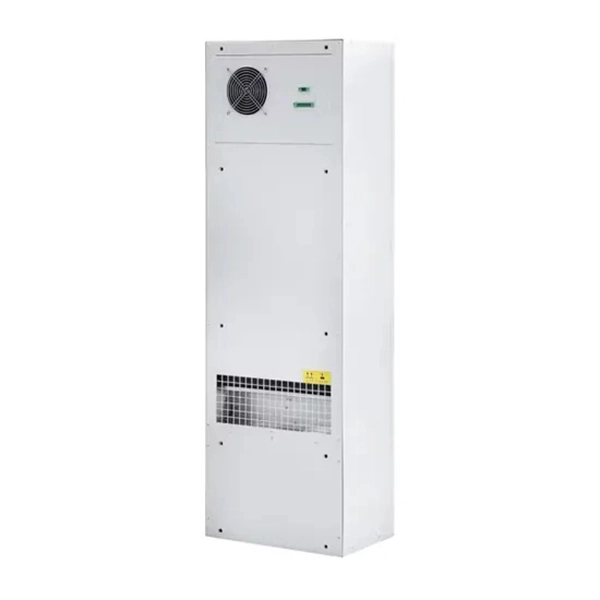
A cable management rack is designed to route, protect, and organize copper and fiber cables inside network cabinets. Beyond keeping cables tidy, a well-structured cable manager reduces cable stress, improves heat dissipation, and ensures bend-radius compliance for data transmission. This article provides a clear technical view of cable management racks, their structures, and how to select the right solution for modern networks. Cable management in server racks simply refers to organizing, routing, and securing power and data cables so they stay neat, accessible, and. Simply put, a cable rack is a structured set of shelves designed to organize, protect, and manage cables in various settings. These racks range from simple, affordable options to complex, high-capacity models that accommodate a vast number of cables. The benefits of using cable racks are numerous. Horizontal cable management is a cornerstone of efficient IT infrastructure, ensuring that server racks and enclosures remain organized, accessible, and functional., Ethernet, fiber optic, coaxial). At its core, it aims to: Minimize cable tangling, kinking, and wear. Simplify troubleshooting and maintenance. As businesses increasingly rely on robust network infrastructure, proper cable organization becomes critical for.
[PDF]

The basic design of an optocoupler consists of a light source, usually an LED (Light-Emitting Diode), driven by the input signal which could be a digital or analogue voltage/current depending upon the characteristics of the light source. An optocoupler (or opto-isolator) is a component that transfer signals between circuits using light. In this guide, you'll learn how they work and how you can use one in your own projects. Optocouplers are very useful when you need to isolate different sections of a circuit, for example in power. Optocouplers, also known as opto-isolators, uses infrared light to transfer electrical signals between two electrically isolated circuits and are commonly classified by their photosensitive output device What is an Optocoupler? An optocoupler (also called an opto-isolator, photo-coupler, or optical. An optocoupler is a tiny part that moves signals between circuits without letting electricity jump across. It uses light to do the job, which helps keep things safe. That way, noisy signals, voltage spikes, or weird grounding issues don't mess with sensitive electronics. Opto-isolators prevent high voltages from affecting the system receiving the signal. We will explore the basics of optocoupler selection and their functionality, helping.
[PDF]
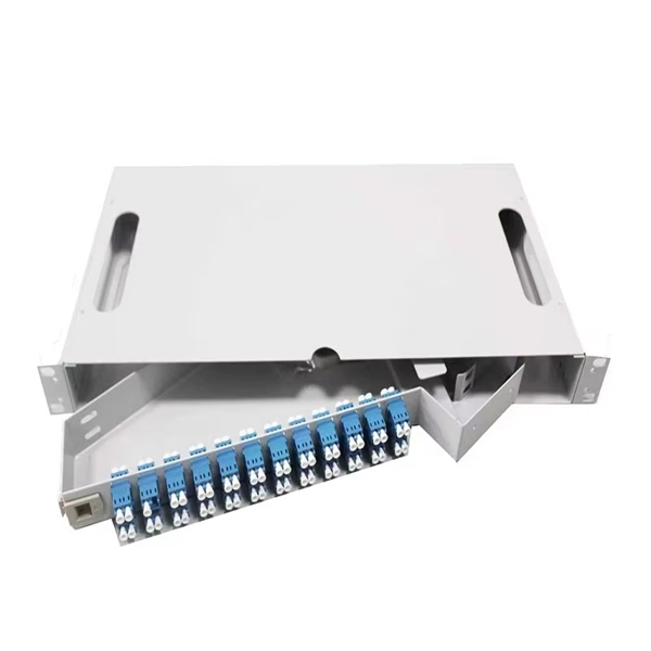
Learn how to splice 4-fiber optic cables using ODF in this complete step-by-step tutorial. Whether you are a beginner or a professional in fiber optic networking, this guide will help you splice fiber cables accurately, manage connections with ODF panels, and ensure. This complete guide explores everything you need to know about ODFs — from their structure, types, and key components, to installation best practices and modern design trends. Whether you're building a central office, data center, or FTTx distribution network, understanding the right ODF. How to Splice 4-Fiber Optic Cable with ODF | Step-by-Step Fiber Optic Splicing Tutorial. This guide demystifies ODF, exploring their design, core functions, types, and how they. An Optical Distribution Frame (ODF) is the central hub for fiber splicing, termination, patching, and cable protection in modern optical networks. It's where incoming and outgoing cables meet. It does four key things: Think of it as the central hub for your fiber network. Without it, cables get tangled. This article explores the types, components, applications, installation, and maintenance best practices, providing a.
[PDF]

Shop our range of high-quality fiber optic attenuators for telecom and datacom applications. Use this optical attenuators buying guide to compare major types, define selection criteria, and find suppliers: 🔬 Encyclopedia article: optical attenuators 📦 Top-level product category: optical components and devices Click on a logo to get to the details of that supplier's offer. Our list of. Find reliable variable optical attenuator prices for various models. FS fixed and variable fiber optic attenuators with leading attenuating fibers guarantee consistent and stable fiber attenuation (0~60dB) in WDM transmission. Optical Attenuators Market report is further segmented By Region (North America, Europe, Asia-Pacific, South America, Middle-East and Africa). In 2024, the market for Optical Attenuators Market was valued at USD 1. It is anticipated to grow to USD 2. 5 Billion by 2033, with a CAGR of 9. The types include VOAs made of 2D MEMS having good repeatability and low cost; VOAs made of 1D MEMS having >70 dB high attenuation; VOAs made of fiber directly coupled to fiber MEMS having ultra-low loss <0. We provide support, services, comprehensive training and the resources you need. It's all part of what we do to maximize the value of your VIAVI investment. Contact us for more information or to receive a price quote. We have the experts.
[PDF]