
It refers to the function that allows network operators to access real-time operational information from optical transceivers. This includes key parameters like temperature, supply voltage, laser bias current, and transmit/receive optical power. This document defines an enhanced Digital Diagnostic Monitoring Interface (DDMI) available in Finisar SFP and SFP+ optical transceivers. ) The interface allows real time access to device operating parameters, and it includes a system. DDM stands for Digital Diagnostic Monitoring (also called Digital Optical Monitoring, or DOM). Defined under the SFF-8472 Multi-Source Agreement (MSA), DDMI ensures compatibility across devices from various manufacturers. By providing real-time data on the state of. This specification is made available for public review at https://www. org/sff/specifications. Comments may be submitted at https://www. Comments received will be considered for inclusion in future revisions of this specification. The. Soft Flags (bits on address 0xA2, byte 110) ofer a mirror of the hard pin state warnings (e. TX Disable, RX SD) accessible via the two-wire serial interface. Related Articles: What is DDMI? How to use DDM information effectively SFF-8636 is an MSA standard that defines.
[PDF]

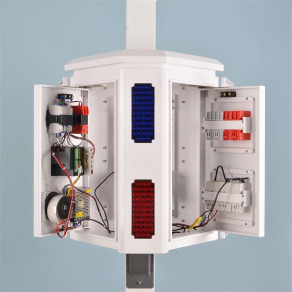
Primary: The main distribution panel, supplies power from the transformer. Differences Between Primary, Secondary, and Tertiary Distribution Boxes Designed for construction or large-scale projects as a main distribution point. Built to meet specific safety and operational standards for temporary construction sites. Incorporates a complete protection system (e. A feeder usually begins with a feeder breaker at the distribution substation. Many feeders leave substation in a concrete ducts and are routed to a nearby pole. At this. The equipment selection depends on the specific power load requirements. These units help control and protect the electrical circuits that serve things like cabin lighting, entertainment, and climate control. The main goal is to keep the primary systems safe while making sure secondary. What Is a Distribution Box? Types, Uses & How to Choose A distribution box, also known as a power distribution box or electrical distribution box, is used to distribute electrical power safely to multiple circuits. It helps organize, protect, and control electrical connections in residential. The main role of a distribution boxes is to channel electric current from the main supply to different circuits within a building. It also helps keep the electricity supply safe by preventing issues like short circuits and overloads. Most distribution boxes contain circuit breakers or fuses that.
[PDF]

Protective relays are essential devices used in electrical power systems to detect faults and abnormal conditions, initiating corrective actions to prevent equipment damage and ensure system stability. These relays play a crucial role in the protection of transformers, generators, transmission. A protective relay is an intelligent device that senses abnormal electrical conditions, such as overcurrent, under-voltage, or frequency deviations. It initiates the operation of circuit breakers to isolate the affected section. This prevents damage to equipment, reduces downtime, and safeguards. Protective relays are critical components in power systems, providing essential protection for various elements such as generator sets, outgoing feeder and load networks, and incoming utility sources. It functions as a watchdog by constantly surveying multiple system components including voltage, current, frequency, and phase angle. It. Protective relays and devices have been developed over 100 years ago to provide “lastline”of defense for the electrical systems. They are intended to quickly identify a fault and isolate it so the balance of the system continue to run under normal conditions. The selection and applications of.
[PDF]
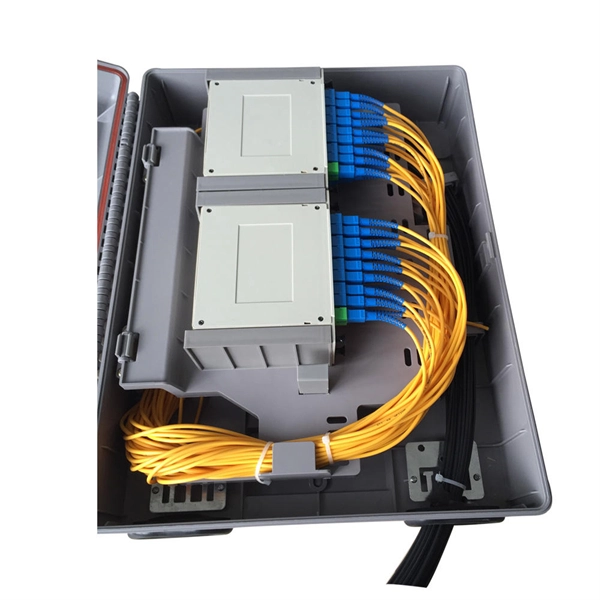
Splice Diagrams or Matrices capture an electric or optical network inside a location – documenting cables, ported equipment, and connections. Splices are fiber-to-fiber, port-to-fiber and port-to-port. Fiber optic cable splicing involves joining two fiber optic cables together. Another method of connecting optical fibers is termination or connectorization, which consists of processing the end of a fiber optic bundle so that it can be connected to other fibers or devices through fiber optic. In this guide, we cover the basics of fiber optic splicing, how to perform splicing using two different methods, and finally some best practices to perform good fiber splicing. Ensure Your Splicing Tools are Clean – #2. Use and Maintain Your. What to show on a network diagram? Fiber optic network diagrams represent the architecture and connectivity of fiber optic systems, and their design philosophy integrates technical, functional, and conceptual aspects. The diagrams abstract complex details of fiber optic systems to make them. This Geoschematics drawing remains easy to read despite containing more than 2000 fibers and 500 splices. All students and instructors must wear safety glasses in this lab. It is copyrighted by the FOA and may not be distributed without FOA permission. This VHO covers similar material to the videos on YouTube. The lab manual has several.
[PDF]

Based on export compliance, verified UL E-files, and consistency in quality control, here are the top 5 Chinese manufacturers producing UL-rated fiber patch cords suitable for enterprise safety in 2025. Before we get to the manufacturers, let's be real about why we are. T&S Communications specializes in a wide range of fiber optic connectivity products, including standard fiber optic patch cords. They offer various types of patch cords, such as simplex, duplex, single-mode, and multi-mode, with different connector options, ensuring high-quality performance for. Fiber optic patch cords are short-distance fiber optic cables used to connect fiber optic equipment. It realizes high-speed and stable data transmission and communication through optical signal transmission. Patch cord has a various application including data centers, network equipment connections. Zhejiang specializes in fiber patch cords and accessories, benefiting from port access for exports. Industrial parks like Wuhan's "Optics Valley" foster R&D partnerships between manufacturers and universities. A “certification” on a. China is home to some of the world's leading fiber optic cable manufacturers, playing a crucial role in global fiber optic communication. As factory-terminated and precisely polished assemblies, they ensure low insertion loss and easy installation. Available in both Singlemode and Multimode configurations, our.
[PDF]

In this article, we will look at a variety of different Ethernet interface types: RJ45, fiber-optic, the common industrial M12 connection, and SFP, which stands for 'small form-factor pluggable. ' The RJ45 port is one of the most common Ethernet setups and is compatible with. Industrial Ethernet switches are the backbone of communication in industries such as transportation, energy, and manufacturing. A vital component of these switches is their interfaces, which facilitate seamless data transmission across a network. This article introduces the types, forms, and. This handy selection guide in PDF format provides you with a comprehensive overview of the extensive range of HARTING products available in the broad market of Industrial Ethernet Connectivity. They are robust, impact-resistant and temperature-resistant. All products fulfill the highest requirements for reliable and flexible industrial Ethernet communication. Unmanaged switches are the simplest active network. WAGO's switch portfolio provides scalable Ethernet network infrastructure with excellent electrical and mechanical performance. These rugged devices are designed for industrial use and are fully compatible with IEEE 802. The WAGO PoE Splitter (Item Number. Ethernet switches can use four different types of connections: RJ45, fiber, M12, and SFP. Understanding the difference can help with network troubleshooting, design, or alteration.
[PDF]

Translation devices, such as Host Bus Adapters (HBA), routers, adapters, gateways, and bridges, are the intermediaries between Fibre Channel protocols and upper layer protocols such as SCSI, FCP, FICON, Ethernet, ATM, and SONET. This section provides information about SAN interfaces, such as, FC ports, Ethernet ports, port groups, and so on. Choose SAN > Interfaces > FC Ports to view information about FC ports. The following. From enabling NVMe and SSD solutions to protecting data integrity, there is a Marvell QLogic Fibre Channel controller capable of delivering the particular technology enhancements, performance, power utilization, and reliability needed for your SAN (storage area network) deployments. Known for its ultra-low latency, lossless transmission, and strong security, FC enables efficient and stable communication between servers and storage systems. A Fibre Channel (FC) interface consists of multiple components that work together to facilitate high-speed data transfer in Storage Area Networks (SANs). The key components include: 1. Storage devices at one end of the fabric store trillions of bits of. Fibre Channel is structured as a set of hierarchical functions, similar to the ISO OSI Reference Model. There are five layers, each being responsible for a certain set of functions or capabilities: Specifies the mapping rules for several legacy upper-layer protocols, allowing Fibre Channel to carry.
[PDF]

Compare fiber optic and copper Ethernet cables across speed, distance, cost, installation difficulty, and use case metrics. Use the interactive scenario selector to find the right medium for your specific network — all processed locally in your browser. PoE Required?. The core difference between fiber optic and copper cables lies in how they carry data. One uses light, the other electricity—and that distinction shapes everything from speed to signal integrity. Fiber optics transmit data as pulses of light through ultra-thin strands of glass or silica. Both technologies can deliver high-speed connectivity, but they behave differently under real-world constraints such as. However, the exponential growth in data demand has positioned fiber optic technology as the superior alternative for performance, scalability, and future-readiness. This article provides a detailed technical comparison between fiber optic and copper cables, offering a clear perspective for. Fiber optic tends to be the more premium solution, while copper wiring is far more common, but why is that? What are the differences between these two cable types, and why might you want to pick one over the other? Here's everything you need to know about fiber vs. copper cables, to help you pick. Several factors are converging to drive the switch from copper to fiber – and cost is a big one. A recent investor presentation by AT&T claimed that fiber was 35% less costly to maintain than copper.
[PDF]
This blog article entry considers the merits of choosing which of various low loss RF coaxial cables to use for IoT, LTE or LORA wireless applications where an external antenna is used to connect to router, gateway or terminal. The choice looks deceptively simple—pick a length, screw it on—but RF engineers know the truth: every extra meter quietly eats away at your link budget, especially once you cross 2 GHz. It's not just about length; the cable type, connector quality, and even mounting environment make a measurable. Audio generated by DropInBlog's Blog Voice AI™ may have slight pronunciation nuances. In this article, we will consider cables such as RG174, RG58, RF195. The cheap connectors have inferior dielectric between the poles as well as poorer grades of metal. The dielectric won't handle high power (KW range) as well and the center pin can more easily shift causing impedance problems if they are moved frequently. RF connectors are usually used with coaxial cables. They are designed to maintain the shielding that the coaxial design offers. The better and newer. Besides the wide range of RF connectors, Telegärtner also provides a considerable range of suitable coaxial low loss cables. Using this one-stop shopping option at Telegärtner makes your purchasing process even more efficient. The main use of low loss cables are all kinds of wireless applications.
[PDF]