
This guide gives a practical, CLI-focused workflow for checking SFP health and diagnostics on Cisco switches, shows the exact commands you'll use, explains what the numbers mean, and compares OEM (Cisco) vs third-party modules so you can pick the right SFP module supplier for. This guide gives a practical, CLI-focused workflow for checking SFP health and diagnostics on Cisco switches, shows the exact commands you'll use, explains what the numbers mean, and compares OEM (Cisco) vs third-party modules so you can pick the right SFP module supplier for. If you run fiber or copper uplinks in a small office, home lab, or data closet, SFPs (and SFP+) are the little parts that keep your links alive. For network engineers, knowing how to view and interpret SFP information from the Cisco command-line interface (CLI) is essential. By checking module. An SFP module (Small Form-factor Pluggable transceiver) is a compact, hot-swappable interface used in switches, routers, and servers to connect network equipment to fiber optic or copper cabling. When optical modules operate on a switch, it is usually necessary to read the module's internal information to understand its working status—such as connection status and real-time metrics like optical power and temperature. Knowing how to view SFP module details helps network engineers verify installation, monitor performance, troubleshoot issues, and maintain.
[PDF]

In this article, we break down the major FTTx models, compare their performance and implementation contexts, and showcase how LINK-PP's high-performance optical modules support each deployment type. Huawei's fiber to the room (FTTR) solution extends fibers to rooms and provides various gigabit Wi-Fi 6 master/slave FTTR units, all-optical components, and optical cable construction tools, enabling users to enjoy stable gigabit Wi-Fi experience in every corner of rooms at every moment. In. Fibre-to-the-room (FTTR) delivers Gigabit optical capacity directly to each room in a building, providing very high-speed, reliable internet. FTTR fibre-based technology: designed to enhance digital capabilities. FTTR addresses challenges related to restricted speeds within buildings, providing. Fiber to the Room (FTTR) is a next-generation access network designed to deliver high bandwidth, low latency, and room-level optical coverage. It is envisaged that the topology and functionalities of FTTR technologies may be. Fiber to the Room (FTTR) is a possible solution to issues with indoor connectivity. Demands for high bandwidth, high bit rates in both directions, low latency, and service reliability are constantly growing. FTTR is a very effective way to improve the quality of residential broadband service and reduce customer complaints, more so with the advent of Wi-Fi 7.
[PDF]
In this video, I have explained and verified the Telnet & SSH configuration on an H3C Switch (Model 6520). As shown in Figure 1, the AC is a Telnet server. Make sure the network connections are available. Click the System View tab at the bottom of the page. From the navigation pane, select System > Resource. On the IPv4. To create a user on an H3C switch, you can perform this operation through a web interface or SSH. Follow the commands below to create a user: Specify the user's access level. The same CLI commands and configuration steps can also be applied to other H3C switch models. You will be in the AUX user interface if you log in through this port. 2 User Interface Number Two kinds of user interface index exist: absolute user interface index and relative user interface index. H3C S5100-SI/EI Series Ethernet Switches Chapter 1 Logging In to an Ethernet Switch 2) A relative user interface index can be obtained by appending a number to the identifier of a user interface type. The relative user interface indexes are as follows: z z. Add the specified port to the current VLAN Configure the link type of the port as Trunk type Allow the specified VLAN to pass through the current Trunk port Set the default VLAN for the trunk port Configure the link type of the port as Hybrid View the VLANs that exist on the current switch View the.
[PDF]
1️⃣ Switch Stacking - Treats multiple physical switches as one logical switch for easier management. These technologies serve different purposes, but they are often used. MLAG vs stacking is frequently discussed in network architecture, as both enable multiple switches to function as a single logical device. While MLAG and switch stacking enhance redundancy, performance, and operational simplicity, their architectural differences can significantly impact network. In the evolution of network device management, switch stacking simplifies management by turning multiple switches into one logical device, making it a popular choice in many networks. But as demands for reliability, scalability, and modern design grow, stacking shows clear limits. It is a scalable solution to expand network capacity while not having trouble managing multiple physical devices. Instead of one cable at 10G, you might have: Of course, as we'll see later, each flow does not get 40G, but in aggregate, you can use all the links. Key goals: What is. This is why you've considered stacking your switches, which allows for efficiency and ease of management—when you do it right. Over the years, stacking has evolved from a premium feature to a core component of an enterprise-grade switch. Within Cisco's lineup, stacking originally began as a feature.
[PDF]

These data switches are responsible for routing and data switching at the core layer of the network. The data routed and switched by the core switch is carried forward to the bottom layers of the network such as the distribution and access layer. Engineered to aggregate massive volumes of data from distribution switches, it provides ultra-low latency and maximum throughput to ensure uninterrupted routing and packet. The significance of the core switch in building and sustaining a resilient network infrastructure is paramount. This determines network efficacy, dependability, and the speed at which. There are different types of enterprise switches that perform various roles in these layer-based or hierarchical ethernet networks. The hierarchy Ethernet network. A core switch in networking serves as the high-capacity backbone, italic centralizing data flow and ensuring efficient communication between different network segments. Simply put, it's the kingpin that keeps your network humming. You may also want to know: Can a Nintendo Switch Play DS Games? ·. A core switch is the backbone of a large-scale network, designed to handle massive volumes of traffic with ultra-low latency and maximum reliability.
[PDF]

This guide explains how to wire a push button switch in a practical way. It covers NO vs NC, what COM does, how a 5-pin LED push button switch is typically arranged, and the most common wiring scenarios. Step-by-step push button switch wiring and installation guide with diagrams, safety tips, and troubleshooting for reliable setup. If you are a DIY builder, installer, or entry-level buyer, this is the wiring logic you can. Wiring a push button switch may seem like a daunting task, but with the right tools and a little bit of knowledge, it can be a simple and straightforward process. It is necessary to understand the steps for wiring these buttons because the right wiring gives you better results and saves you from any harm. In this blog, you will get complete guidance on wiring a push. Hey, in this article we are going to see the Single Phase Distribution Box Wiring Diagram and Connection Procedure. A distribution board or distribution box is where the main power supply is distributed to multiple loads. The main components of a push button switch are the button itself, which is usually made of plastic or metal, and the switch mechanism, which is responsible for.
[PDF]
OSFP, or Octal Small Form-factor Pluggable, is a high-speed transceiver form factor designed for next-generation data center networking. Compared with previous generations of optical modules, OSFP is optimized for higher bandwidth, better thermal performance and denser port. Among the various 400G optical transceiver form factors, OSFP stands out as a next-generation form factor specifically designed for high-speed Ethernet, offering clear advantages. This article introduces the fundamental concept and key characteristics of 400G OSFP Ethernet optical transceivers, and. Optech, a Taiwan-based optical transceiver manufacturer, provides professional 400G OSFP and 800G OSFP solutions designed for AI, cloud, high-performance computing, data center and advanced networking applications. Understanding MSA is critical for compatibility validation, cost. As data centers transition from 400G to 800G interconnects, bandwidth demand, power efficiency, and thermal constraints have forced the industry to look beyond traditional form factors. Designed to support 400 Gigabit Ethernet transmission with improved thermal performance and higher power capacity, OSFP modules are widely adopted.
[PDF]

The switch is a PoE switch and supports three power module slots, each of which can have a 1000 W PoE or 600 W PoE power module installed. Pluggable AC and DC PoE power modules can be used together in the same switch. A RTU license (L-P1GUPG10G-S57S) can be loaded to increase the port rate to 10 Gbit/s. In V200R024C00 and later versions, 1000BASE-X ports can be configured to work at 2. 5 Gbit/s using the port mode 2. 5. The Alta Labs S48-APOE features full PoE+ connectivity on all 48 ports. It features a PoE budget of 740 watts and provides up to 30 watts of power per port. The first 32 Ethernet ports support up to 1 Gbps connections, while the last 16 Ethernet ports support up to 2. The. The Huawei S5731-S48P4X is a high-performance switch from the Huawei S5700 series, designed to meet the networking needs of modern enterprises. It features 48× 10/100/1000BASE-T ports and 4× 10GE SFP+ uplink ports, providing reliable and scalable connectivity. Designed for flexibility, it delivers a massive 740W PoE budget to power a wide range of connected devices including access points, IP cameras, and VoIP. 48 PoE+ Ports with High Power Budget – Features 48 total PoE+ Ethernet ports: 32× 1GbE and 16× 2. 5GbE, delivering up to 740W of total PoE+ power for IP cameras, access points, VoIP phones, and more. Manage from Anywhere with Alta Cloud – Easily monitor and control your network from your phone or.
[PDF]
Calculate US import duties, processing fees, and total landed costs. Powered by official USITC Harmonized Tariff Schedule data. Automatically applies additional. The Harmonized Tariff Schedule of the United States (HTS) sets out the tariff rates and statistical categories for all merchandise imported into the United States. This ad valorem duty stacks on existing Section 301 and Section 232 tariffs currently in effect. We will. The items concerned are referred to as the TL-SG108 desktop switch, the TL-SG1008PE desktop or rack-mountable switch, the TL-SG116E desktop or wall-mountable switch, the TL-SG1016DE desktop or rack-mountable network switch, and the TL-SG1016PE desktop or rack-mountable network switch. These. After Trump Tariffs Based on estimates from the Tax Foundation, Yale Budget Lab, and Penn Wharton Budget Model This US tariff calculator helps you estimate the cost of importing goods under the current Trump tariff regime. Whether you're importing from China, the EU, or anywhere else, use it to. Here's What That Means for Prices. Last updated 2 months ago. Our resources are updated regularly but please keep in mind that links, programs, policies, and contact information do change.
[PDF]

In this article, we will look at a variety of different Ethernet interface types: RJ45, fiber-optic, the common industrial M12 connection, and SFP, which stands for 'small form-factor pluggable. ' The RJ45 port is one of the most common Ethernet setups and is compatible with. Industrial Ethernet switches are the backbone of communication in industries such as transportation, energy, and manufacturing. A vital component of these switches is their interfaces, which facilitate seamless data transmission across a network. This article introduces the types, forms, and. This handy selection guide in PDF format provides you with a comprehensive overview of the extensive range of HARTING products available in the broad market of Industrial Ethernet Connectivity. They are robust, impact-resistant and temperature-resistant. All products fulfill the highest requirements for reliable and flexible industrial Ethernet communication. Unmanaged switches are the simplest active network. WAGO's switch portfolio provides scalable Ethernet network infrastructure with excellent electrical and mechanical performance. These rugged devices are designed for industrial use and are fully compatible with IEEE 802. The WAGO PoE Splitter (Item Number. Ethernet switches can use four different types of connections: RJ45, fiber, M12, and SFP. Understanding the difference can help with network troubleshooting, design, or alteration.
[PDF]

Mechanical Optical Switches: Switching times typically range from 1-10ms, suitable for long-distance transmission scenarios where latency is not critical (such as backbone network protection switching). Solid-State Optical Switches: Based on thermooptic or electrooptic effects, response. We lead the industry in optical switch technology, delivering the lowest insertion loss (0. 2 dB), fastest switching speed (10 ns), broadest wavelength range (300–2400 nm), widest fiber compatibility, highest optical power handling (50 W), and space-qualified reliability. Backed by over 25 years of. Use this optical switches buying guide to compare major types, define selection criteria, and find suppliers: Professional purchasing of high-value photonics products is a substantial responsibility, where a structured decision-making process is essential. RP Photonics offers a lot of help: Get. This document is a troubleshooting and selection guide for common optical switch failures, compiled based on over 500 field cases. These switches are built on proven, reliable optomechanical technology that has seen more than 30 years of successful operation. Each. The POLATIS ® Series 7000 384x384 all-optical circuit switch is designed to meet the most demanding applications with exceptionally low optical loss, compact size, and fast switching speeds. With support for Software-Defined Networks (SDNs) via embedded NETCONF and RESTCONF control interfaces, the.
[PDF]

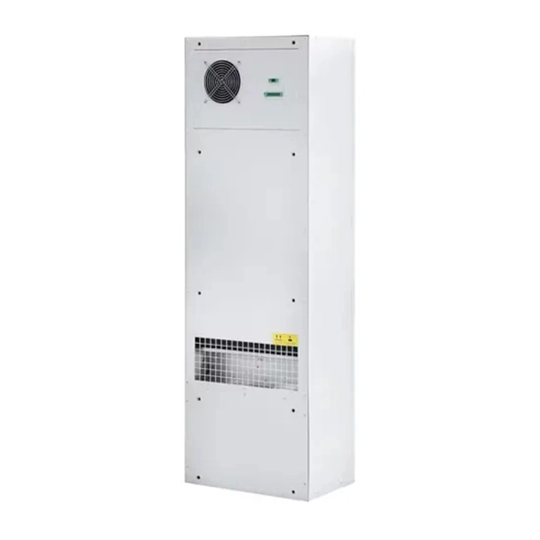
The use of locking cabinets with advanced steel and tamper-resistant designs utilizes physical barriers to limit access to sensitive materials, making them harder to reach for unauthorized individuals. This pressure can cause the gap below server cabinets, which is often 2” or more, to become an air stream between hot and cold aisles. The resulting mix of air reduces the effectiveness of a containment solution. The Cool Shield Magnetic Cabinet Skirt provides an easy fix for this issue. These. Commercial environments have evolved as technology advances, and having a robust cabling infrastructure is crucial for scalability, minimising downtime, and enhancing productivity. Educational institutions are increasingly adopting smart technologies and cloud-based resources, so the foundation of. Many network devices are stored in the cabinets. In order to meet the normal operation of these devices in the cabinets, when the computer room cabinets are full of various cabinets and devices, we need to consider how to place the network cabinets? 1. Network cabinet placement skills (1) Before. A network cabinet is defined as a physically enclosed compartment built to store networking gadgets like patch panels, modems, switches, and a multitude of cables. Network cabinets support large, modular network switches by providing additional space for cable management and side-to-side airflow solutions. Networking cabinets tend to have.
[PDF]

Islamabad, October 31, 2024 – Jazz, Pakistan's leading digital operator and a member of the VEON Group, has taken a significant leap in advancing the nation's telecommunications infrastructure by deploying a 400G IP-based RAN Access Optical Network in collaboration with Huawei. Islamabad, October 31, 2024 – Jazz, Pakistan's leading digital operator and a member of the VEON Group, has taken a significant leap in advancing the nation's telecommunications infrastructure by deploying a 400G IP-based RAN Access Optical Network in collaboration with Huawei. Huawei Technologies and Transworld Associates announced the successful deployment of Pakistan's first 400G optical network, a major milestone in the nation's digital infrastructure development. The cutting-edge network spans 72 sites nationwide, underscoring both companies'. Islamabad: In a landmark step toward Pakistan's digital transformation, Huawei Technologies and Transworld Associates on Wednesday afternoon announced the successful deployment of the country's first 400G optical network, significantly enhancing connectivity across the China-Pakistan Economic. Huawei provided a 400G solution designed for high bandwidth and low per-bit cost. Key features include: a. A CDF network architecture enables smooth evolution to higher speeds (400G+ and beyond) while facilitating L-band expansion for enhanced capacity. Delivering 400G per wavelength, each fiber.
[PDF]