Available in five IT load configurations from 18 to 90kW, this modular data center supports fast rollout, high reliability, and seamless integration—ideal for large-scale deployments and future-ready data center solutions. Delta InfraSuite is a new generation, highly integrated modular datacenter solution. It uses racks as the datacenter carrier and fully integrates all sub-systems including UPSs, cooling, power distribution, lightning protection, fire control (optional), wiring, airflow management, intelligent. The Delta Xubus Node is a prefabricated modular data center designed to meet this need—offering an offsite-built, plug-and-play solution that combines power distribution, cooling systems, and critical IT infrastructure into a factory-tested unit. As a global leader in thermal and power management solutions, Delta has further strengthened its leading position in data center infrastructure with a.
[PDF]

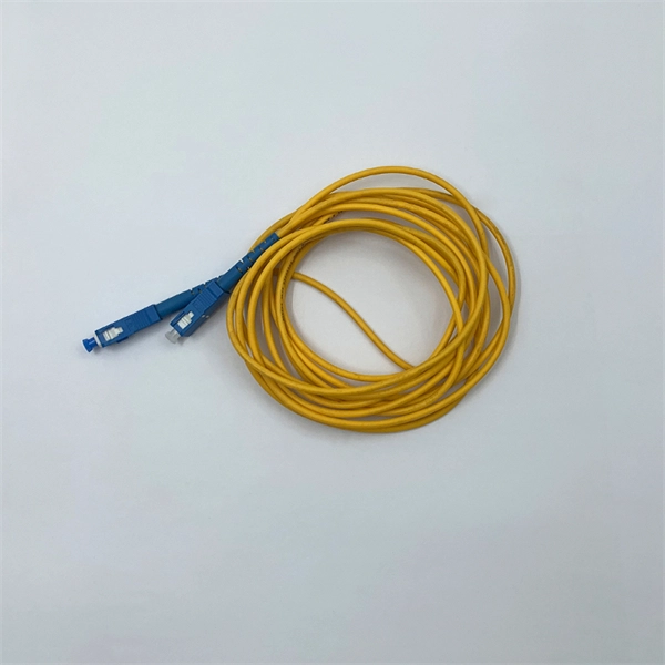
In practice, there are two main ways to terminate fiber optic cable: using a connector to join two fibers to create a temporary, removable joint, or using splicing technology to permanently join two bare fibers directly. Either. Terminating fiber optic cables essentially means putting connectors on fiber optic cable so that you can connect the cable to various devices or network components. Think of it as the equivalent of connecting the dots in a complex puzzle; without proper termination, the whole system can break down. Fiber optic networks are the backbone of modern communication systems, enabling high-speed data transfer and reliable connectivity. When deploying fiber optic cabling, one of the most critical decisions is how to terminate the fiber—either by splicing or using connectors. The process of fiber optic cable termination is the essential act of connecting fiber optic cables to devices, patch panels, or other cables to enable. This Applications Engineering Note explains how different optical fiber termination methods impact the optical performance of telecommunications systems. Optical fiber cabling systems support various communications technologies that use digital as well as analog signaling. This involves either installing a connector or creating a splice to establish a reliable connection point for the optical signal.
[PDF]

This tool is designed to convert the lines into (Pipes, Ducts, Conduits and Cable Trays) from CAD exploded (2d or 3d) lines or from Autodesk® Revit® lines. The tool will. If you're a Revit user looking to speed up your workflow when converting CAD lines into pipes, ducts, conduits, and cable trays, then the "Create (Pipes, Ducts, Conduits and Trays) from CAD" plugin is the solution you've been searching for. This powerful tool is designed to automate the process of. Download a comprehensive set of Cable Tray Installation CAD Blocks in DWG format, ideal for electrical engineers, MEP designers, and industrial layout planners. The tool will. Discover all CAD files of the "Cable trays" category from Supplier-Certified Catalogs ✅ SOLIDWORKS, Inventor, Creo, CATIA, Solid Edge, autoCAD, Revit and many more CAD software but also as STEP, STL, IGES, STL, DWG, DXF and more neutral CAD formats. Free CAD and BIM blocks library - content for AutoCAD, AutoCAD LT, Revit, Inventor, Fusion 360 and other 2D and 3D CAD applications by Autodesk. CAD blocks and files can be downloaded in the formats DWG, RFA, IPT, F3D. You can exchange useful blocks and symbols with other CAD and BIM users.
[PDF]
The Americas Region Caribbean Ring System (ARCOS-1) is a of 8,400 kilometers that extends between the, the, the, the,,,,,,,,,,, and. Because of its length, it was divided in two phases: Phase 1 being in service since September 2001 and Phase II since March 2002. The cable system wa.
[PDF]

For installation, it is best to use a regular distribution box. If there is no distribution box, you can also purchase a card slot for fixing the air switch at the air switch store. Fix the card slot on a wooden board or a wall, and then install the air switch on it. A distribution board or distribution box is where the main power supply is distributed to multiple loads. Single Phase Distribution Box generally consists of Double Pole MCBs, Single Pole MCBs, and RCCBs. Whether you're an electrician or a DIY enthusiast, this guide will help you understand the basics of home electrical distribution. What is Distribution Board? Distribution board. 1, the general switch of the household distribution box can generally choose double-pole 32-63A small air switch or isolation switch. 2、Lighting circuits generally use 10-16A small air switches. air conditioning circuits generally choose. An electrical panel box, also known as a breaker box or a distribution board, is a crucial component of any electrical system. Arrangement order: The circuit breakers should be arranged from left to right, and the reserved position is generally placed on the right side of the distribution box. Wire color: The neutral wire is blue, and the color of the phase wire (A phase is yellow, B phase is green, and C phase is red).
[PDF]

They are designed to split unpolarized light at a specific Reflection/Transmission (R/T) ratio with unspecified polarization tendencies. A beam splitter or beamsplitter is an optical device that splits a beam of light into a transmitted and a reflected beam. It is a crucial part of many optical experimental and measurement systems, such as interferometers, also finding widespread application in fibre optic telecommunications. This division allows for the simultaneous analysis or utilization of the light's properties along two separate paths. The device is purely. Transmission and Reflection by. In addition to the task of dividing light, beamsplitters can be employed to recombine two separate light beams or. Explore the precision, applications, and design principles of beam splitters, essential for advancements in scientific research and technology. With WDS, a single X-ray energy – monochromatic X-rays – are counted at any given time. 19511; JEOL L-Value table2; CAMECA® SXFiveFE brochure3; Oxford Instruments Wave brochure4; Thermo ScientificTM NORANTM IbeX5). Unlike conventional beam splitters, PBSs ensure that the resulting beams are both linearly.
[PDF]