How does a passive optical network work? A PON system consists of an optical line terminal (OLT) at the communication company's central office and several optical network units (ONUs) near end users. Typically, up to 32 ONUs can be connected to a single OLT. This paper presents the design and implementation of a passive optical network (PON) based on a gigabit-capable passive optical network (GPON) standard to deliver fiber-to-the-home (FTTH) services in a small-town setting. The proposed solution prioritizes cost-effectiveness, scalability, and. Passive optical networking (PON), like active optical networking, uses fiber-optic cabling to provide Ethernet connectivity from a main data source to endpoints. While there are many subtle differences, a clear distinction between active optical networking and PON topology is PON's use of a. Network designers and ISPs aiming for efficiency must focus on effective passive optical network design, with careful consideration of PON architecture planning and splitter placement. Instead of running a separate fiber strand to every home or office, a PON shares a single fiber using optical. Passive Optical Network (PON) technology is finding its way deep into the Local Area Network (LAN) to provide significant features, benefits and cost savings to large businesses and organizations. This is particularly true for the Gigabit PON (GPON) flavor, which is standardized by the.
[PDF]

Key components of a Passive Optical Network include the Optical Line Terminal (OLT), Optical Network Unit (ONU) or Optical Network Terminal (ONT), Optical Distribution Network (ODN), and Optical Splitters. An OLT is a device used to interface between the service provider's central. The designation “passive” separates these components from active devices, such as lasers, amplifiers, or switches, which rely on electrical power to boost, regenerate, or electronically route a signal. Passive components operate solely by exploiting the fundamental physical properties of light. PON primarily utilizes a point-to-multipoint topology and fiber optical splitters to transmit data from a single point of transmission to multiple user endpoints. The key advantages of PON lie in its ability to offer remote, high-bandwidth, and efficient network connections. Key components of a. Some of the most common optical passive components include optical couplers, optical splitters, optical filters, optical connectors, optical attenuators, optical circulators, optical isolators, optical switches, and optical add/drop multiplexers. A. A device in a passive optical network is something that the transceiver transmits information through, like a modem that sends information through fiber-to-the-home. By eliminating powered components between the service.
[PDF]
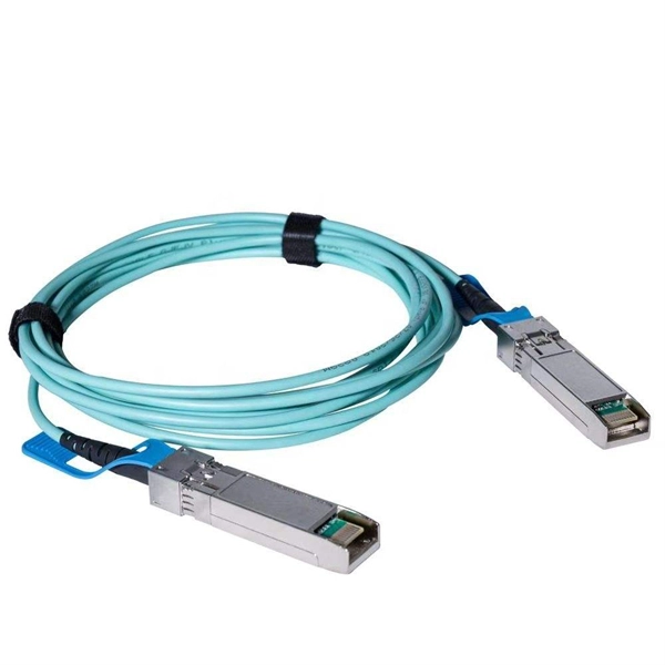
In today's data-driven world, high-speed optical modules (e., 100G/400G/800G) are the backbone of modern networks, enabling ultra-low latency and massive bandwidth for data centers, telecom, and enterprise applications. However, their performance hinges on proper deployment. nd Latency variation are very important in applications requiring accurate timing (e (PAM-4 or Coherent), require complex digital signal processors (DSPs) in optic itional EEPROM data content for propagation del ss C. 2” pluggable : 2% of the cTE budget ITU-T G. 2 allocated for Class C A. 20”. This article helps trading engineers and network architects select an ultra low latency SFP that fits 10G/1G optics needs while minimizing added propagation and serialization delay. A solution for accurately measuring the Latency of PAM4 optical modules is required. Potential source of time error in complex digital parts of pluggables. Higher bit rates (50 Gb/s and higher) and. Transceiver latency is a key spec in enterprise fiber optic networks especially in financial institutions. It is the one of the few variables that can be optimized since fiber path delay is fixed. However, their performance hinges on proper deployment and maintenance.
[PDF]
OSFP, or Octal Small Form-factor Pluggable, is a high-speed transceiver form factor designed for next-generation data center networking. Compared with previous generations of optical modules, OSFP is optimized for higher bandwidth, better thermal performance and denser port. Among the various 400G optical transceiver form factors, OSFP stands out as a next-generation form factor specifically designed for high-speed Ethernet, offering clear advantages. This article introduces the fundamental concept and key characteristics of 400G OSFP Ethernet optical transceivers, and. Optech, a Taiwan-based optical transceiver manufacturer, provides professional 400G OSFP and 800G OSFP solutions designed for AI, cloud, high-performance computing, data center and advanced networking applications. Understanding MSA is critical for compatibility validation, cost. As data centers transition from 400G to 800G interconnects, bandwidth demand, power efficiency, and thermal constraints have forced the industry to look beyond traditional form factors. Designed to support 400 Gigabit Ethernet transmission with improved thermal performance and higher power capacity, OSFP modules are widely adopted.
[PDF]

Islamabad, October 31, 2024 – Jazz, Pakistan's leading digital operator and a member of the VEON Group, has taken a significant leap in advancing the nation's telecommunications infrastructure by deploying a 400G IP-based RAN Access Optical Network in collaboration with Huawei. Islamabad, October 31, 2024 – Jazz, Pakistan's leading digital operator and a member of the VEON Group, has taken a significant leap in advancing the nation's telecommunications infrastructure by deploying a 400G IP-based RAN Access Optical Network in collaboration with Huawei. Huawei Technologies and Transworld Associates announced the successful deployment of Pakistan's first 400G optical network, a major milestone in the nation's digital infrastructure development. The cutting-edge network spans 72 sites nationwide, underscoring both companies'. Islamabad: In a landmark step toward Pakistan's digital transformation, Huawei Technologies and Transworld Associates on Wednesday afternoon announced the successful deployment of the country's first 400G optical network, significantly enhancing connectivity across the China-Pakistan Economic. Huawei provided a 400G solution designed for high bandwidth and low per-bit cost. Key features include: a. A CDF network architecture enables smooth evolution to higher speeds (400G+ and beyond) while facilitating L-band expansion for enhanced capacity. Delivering 400G per wavelength, each fiber.
[PDF]

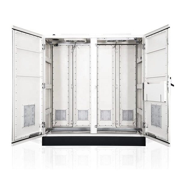
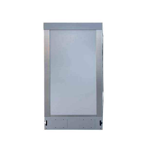
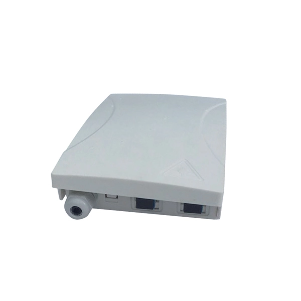
Splice boxes keep joints of fiber-optic cables safe from external stress and manage excess cable lengths. They are also referred to as Optical Termination Boxes. The GZR Series 19" Rack-mounted Terminal Box (Rail-based) is a functional component for optical fibre distribution frames or network integrated cabinets, offering fibre splicing, distribution, and tray storage. CAHORS offers complete solutions for FTTH distribution in residential. OTRANS provides professional, high-quality rack mount fiber patch panels (also known as fiber termination boxes) designed for modern data centers and network infrastructure. Our comprehensive range, from 1U to 4U standard 19-inch panels, offers scalable port densities (12 to 96 ports) to meet your. Distribution Cabinet Box – The Multi-Operator cabinet is a grouping module for fusion, coupling and connection of up to 48 fibers. Our boxes serve as a connection point for incoming and outgoing cables, providing cable termination, organization, and protection. GAO's box includes features such as cable. With the growing global deployment of Fiber-to-the-Home (FTTH) networks driven by the demand for ensuring high-capacity broadband services, mobile network operators (MNOs) face challenges of excessive energy consumption (EC) of wired optical access networks (OANs). This paper presents a.
[PDF]

DFM in optical design refers to the process of designing optical components and systems that are manufacturable, testable, and inspectable. The importance of DFM lies in its ability to reduce production costs, improve product quality, and accelerate time-to-market. The SPIE Digital Library's coverage of design for manufacturability (DFM) predominantly centers on semiconductor and optical system manufacturing. The content heavily emphasizes photolithography-related DFM, detailing techniques for optimizing mask designs, optical proximity correction, and. Design for manufacturability (DFM) is a critical first step in the development of any optical component. In the context of optics, DFM involves optimizing the design of optical components and systems to minimize production costs, reduce. Optical assembly manufacturing combines precision components such as lenses, prisms, mirrors, and other components that must perform in demanding environments. Taking complex optical systems from simulation into production involves meeting a range of mechanical, functional, and other requirements. Today, we are expanding my very first blogpost from 2020 and discussing the concept of Design for Manufacturability (DFM). In this article, we explore why DFM matters and how key design aspects influence the success of plastic optics. Understand the Limitations of Injection Molding.
[PDF]

Optical attenuators use several principles in order to accomplish the desired power reduction. The types of attenuators generally used are fixed, stepwise variable, and. An optical attenuator is a passive device that is used to reduce the power level of an optical signal. The attenuator circuit will allow a known source of power to be reduced by a predetermined factor, which is usually expressed as decibels. Key requirements include minimal effect on the beam profile, low wavelength and polarization dependence, and sufficient power handling capability. The basic types of optical attenuators are fixed, step-wise variable, and continuously variable. Since too much light may saturate the fiber optic receiver, optical attenuators are often deployed in the system to reduce the light power and achieve the best fiber. An attenuator is a device designed to reduce the intensity of electrical and electromagnetic oscillations smoothly, stepwise, or at a fixed rate. It primarily ensures the power or amplitude of a signal is lowered without significantly distorting its waveform. Attenuators are extensively used across.
[PDF]
In this paper, we present this new method of building OMS-OOCCN or its model. System design Our method applies three key information processing techniques such as geographic information system (GIS), simulation and expert system (ES) ones. We developed a specialized Geographic Information System for an internet service provider operating a fiber-optic network across multiple neighboring locations. Really, they are also the most important techniques for. Location Data (C. Summary of descriptive data (C. Manage Fiber Optics Network (maintenance &operation) (C. Final. A leading telecom infrastructure provider responsible for planning, deploying, and maintaining optical fibre cable (OFC) networks to expand digital connectivity across urban and rural regions. The client needed a reliable and accurate system to document, monitor, and manage thousands of kilometers.
[PDF]
An optical ground wire (also known as an OPGW or, in the IEEE standard, an optical fiber composite ) is a type of cable that is used in. Such cable combines the functions of and. An OPGW cable contains a tubular structure with one or more in it, surrounded by layers of and. The OPGW cable is run between the tops of high-voltage. The part of the cable serves to bond adjacent tow.
[PDF]
The communication system of fiber optics is well understood by studying the parts and sections of it. The major elements of an optical fiber communication system are shown in the following figure. The ba.
[PDF]

This paper will review the development of fiber-optic high-temperature sensors over the last 30 years, presenting their design and fabrication methods according to sensing type and typical temperature measurement performance. The full paper consists of eight sections. Fiber-optic high-temperature sensors are gradually replacing traditional electronic sensors due to their small size, resistance to electromagnetic interference, remote detection, multiplexing, and distributed measurement advantages. This paper reviews the sensing principle, structural design, and. Luna's Optical Backscatter Reflectometer (OBR) products are based on OFDR and provide a level of detail and precision not available with the prevailing fiber optic diagnostic tool - the optical time domain reflectometer (OTDR). OBR systems map out loss along a single-mode fiber (SMF) or multi-mode. breadth and most comprehensive solutions for optical communications test products to be found in one place. Corning's High Temperature Fibers are designed for applications requiring improved fatigue resistance, high usable strength, and excellent resistance to higher temperatures and hydrogen permeation. Thus, wireless communication -situ processing of data would combined with in significantly improve the ability to include sensors into high temperature systems and thus lead toward more intelligent engine systems. NASA Glenn Research Center (GRC) is presently lea, communication systems,ding the.
[PDF]

Insertion loss tells you how much weaker the signal becomes after passing through the splitter. Let's say you have a laser output at 0 dBm (which is 1 milliwatt of optical power). If you use a 1×8 splitter with ~10. 5 dB of insertion loss, the power at each output would be: 0 dBm – 10. 5. Enter excess loss from the splitter datasheet for your wavelength. Add connector and splice quantities with realistic planning losses. Include any additional component losses and an engineering margin. Enable power budget to estimate received power and margin. Press Calculate to show results above. Understanding optical splitter loss isn't just about plugging numbers into a calculator. It's about knowing what factors contribute to that loss, how manufacturers specify it, and how it impacts the overall performance and reach of your network. Ignore it, and you might find your signal too weak to. Optical insertion loss refers to the signal loss resulting from the insertion of components such as connectors or splices in an optical fiber system. Common ratios: For cascades, add losses and validate margin using the Optical Budget tool. This Fiber Optic Splitter Insertion Loss is the splitter devices loss, Considering fiber connectors or connectors+adapter insertion loss in LGX, The fiber splitter IL would be a little bigger. To make clear the basic ftth fiber splitter loss in performance, You can refer to the below loss chart.
[PDF]