Single-mode optical splitters are optimized for single-mode optical fiber, while multimode optical splitters are tailored for use with multimode optical fiber. An Optical Splitter, also known as a beam splitter, is a passive optical device that divides a single input optical signal into two or more output signals. Conversely, it can also combine multiple signals into one. Its primary role is in Passive Optical Networks (PON), which are the foundation of. This guide demystifies fiber optic splitters, explaining their design, operating principles, types, key specifications, and real-world applications. It can distribute the optical energy transmitted through a single fiber to two or more fibers in a predetermined ratio or combine the optical energy from multiple fibers into one fiber. “Passive” means it needs no. You use optical couplers and splitters to split or join signals in fiber networks. For example, optical splitters send light to many output ports. This lets you connect more users to one network terminal. There are different types of fiber optic splitters available, with two of the most common being Fused Biconical Tapered (FBT) splitters and Planar Lightwave.
[PDF]
It is currently used in modern three-CCD cameras. An optically similar system is used in reverse as a beam-combiner in three- LCD projectors, in which light from three separate monochrome LCD displays is combined into a single full-color image for projection.OverviewA beam splitter or beamsplitter is an that splits a beam of into a transmitted and a reflected beam. It is a crucial part of many optical experimental and measurement systems, such as. In its most common form, a cube, a beam splitter is made from two triangular glass which are glued together at their base using polyester,, or urethane-based adhesives. (Before these synthetic,. Beam splitters are sometimes used to recombine beams of light, as in a. In this case there are two incoming beams, and potentially two outgoing beams. But the amplitudes.
[PDF]

Insertion loss tells you how much weaker the signal becomes after passing through the splitter. Let's say you have a laser output at 0 dBm (which is 1 milliwatt of optical power). If you use a 1×8 splitter with ~10. 5 dB of insertion loss, the power at each output would be: 0 dBm – 10. 5. Enter excess loss from the splitter datasheet for your wavelength. Add connector and splice quantities with realistic planning losses. Include any additional component losses and an engineering margin. Enable power budget to estimate received power and margin. Press Calculate to show results above. Understanding optical splitter loss isn't just about plugging numbers into a calculator. It's about knowing what factors contribute to that loss, how manufacturers specify it, and how it impacts the overall performance and reach of your network. Ignore it, and you might find your signal too weak to. Optical insertion loss refers to the signal loss resulting from the insertion of components such as connectors or splices in an optical fiber system. Common ratios: For cascades, add losses and validate margin using the Optical Budget tool. This Fiber Optic Splitter Insertion Loss is the splitter devices loss, Considering fiber connectors or connectors+adapter insertion loss in LGX, The fiber splitter IL would be a little bigger. To make clear the basic ftth fiber splitter loss in performance, You can refer to the below loss chart.
[PDF]
Explore the precision, applications, and design principles of beam splitters, essential for advancements in scientific research and technology. Beam splitters are integral optical components that divide a beam of light into two or more separate beams. There are two basic types of beamsplitters: Non-polarizing beamsplitters (NPBS): This type of splitter is used to divide (split) a beam into two beams and each output beam is a fraction of the incoming beam regardless of the polarizations. Non-polarizing beamsplitters are used in a variety of. 📦 For purchasing, use the RP Photonics Buyer's Guide for beam splitters. It provides an expert-curated supplier directory, buyer-focused technical background information, and structured selection criteria to support professional procurement decisions. What are Beam Splitters? A beam splitter (or. As a basic and important link in on-chip photon propagation, beam splitting is of great significance for the efficient utilization of sources and the compact integration of optoelectronic devices. It is widely used in power splitting, polarization separation, wavelength division multiplexing and. The SPIE Digital Library offers a wide range of resources on beam splitters, focusing on their design, applications, and performance across various optical systems. The principle of beam splitting is based on the manipulation of light waves using various optical materials and coatings. Their precision and versatility make them.
[PDF]

A polarizing beamsplitter is a type of beamsplitter that splits unpolarized light into S- and P- Polarization states. Beamsplitters can also be used in reverse to combine two different beams into a single one. They can be classified into different types depending on their construction: cube, plate. A beam splitter cube is a key component of a Polarizing Beam Splitter, also known as a polarization beam splitter or polarized beam splitter. Typically configured as a cube, it avoids ghost images and ensures clean. A PBS is an optical device that splits a beam of light into two separate beams with orthogonal (perpendicular) polarizations. Understanding the principles, types, and applications of PBS is essential for designing and optimizing optical systems. Unlike conventional beam splitters, PBSs ensure that the resulting beams are both linearly. INSTITUTIONAL Select your institution to access the SPIE Digital Library. No SPIE Account? Create one A compact and broadband polarization beam splitter (PBS) based on silicon (Si) nitride (SiN)-on-Si-on-insulator multilayer platform with vertical asymmetrical directional coupler (ADC) is designed.
[PDF]
Beamsplitters are commonly employed in lasers to create different beam paths, achieving this effect by dividing the laser beam into multiple segments and then recombining them. This allows the direction and intensity of the beam to be adjusted with outstanding precision and. Beamsplitters are fundamental components in optical engineering, serving to precisely divide a single input beam of light into two distinct output beams. This division allows for the simultaneous analysis or utilization of the light's properties along two separate paths. It is a crucial part of many optical experimental and measurement systems, such as interferometers, also finding widespread application in fibre optic telecommunications. In its. This article explains how to create a beam splitter cube in Sequential Mode. One of the biggest challenges for modeling such a system is that multiple ray paths cannot be simultaneously traced in Sequential Mode. These versatile tools can split both laser and regular light, depending on the application in question. Beamsplitters are often classified according to their construction: cube or plate. Beam splitter divides a beam of light into two or more separate beams. Beam splitters can be made from different materials and are often coated with thin layers of metal or dielectric materials.
[PDF]

At the core of a beam splitter's functionality is its ability to split an incoming light beam into multiple paths. This is typically achieved through processes of refraction, reflection, or diffraction. It is a crucial part of many optical experimental and measurement systems, such as interferometers, also finding widespread application in fibre optic telecommunications. In its. 📦 For purchasing, use the RP Photonics Buyer's Guide for beam splitters. It provides an expert-curated supplier directory, buyer-focused technical background information, and structured selection criteria to support professional procurement decisions. This passive device uses a specialized surface designed to both reflect and transmit light simultaneously. The resulting beams are directed along different paths, allowing a single light. Beam splitters are essential optical components used to divide a beam of light into two or more separate beams. They play a crucial role in various scientific, industrial, and everyday applications. Its fundamental purpose is to precisely control the path and intensity of light, making it a ubiquitous component across various optical systems.
[PDF]
This occurs because when s-polarized light hits the reflecting surface, the electric field is in the same plane as the surface. The set up is either: Camera lens - beam splitter - camera x2 Or, Beam splitter - (lens + camera) x2 I want to be able to take 2x photos at once, so the light has to go through the beam splitter. I used the polarised flexible sheet as a proof on concept, which worked but need to make it more. A beam splitter or beamsplitter is an optical device that splits a beam of light into a transmitted and a reflected beam. It is a crucial part of many optical experimental and measurement systems, such as interferometers, also finding widespread application in fibre optic telecommunications. Additionally, beamsplitters can be used in reverse to combine two different beams into a single one. The resulting beams are directed along different paths, allowing a single light. 📦 For purchasing, use the RP Photonics Buyer's Guide for beam splitters. It provides an expert-curated supplier directory, buyer-focused technical background information, and structured selection criteria to support professional procurement decisions. What are Beam Splitters? A beam splitter (or. am Splitters/Combiners. This document describes this product line, as well as general operation guidel into two output beams t beams of equal power. The standard product is designed for use in the visible spectrum 400-700 nm wavelength). The cube can only be effectively used as a splitter; used.
[PDF]
We present an extensive study of an ultra-compact grating-based beam splitter suitable for photonic integrated circuits (PICs) which have stringent density requirements. In this paper, we propose a one-dimensional polarization beam splitting grating under normal incidence with excellent polarization characteristics and a high diffraction efficiency. The main structure is a double-groove slanted grating. The 10 m long beam splitter exhibits equal splitting, low insertion loss, and also provides a high extinction ratio in an. In this work, a reflective beam-splitter based on a metallic Ronchi diffraction grating normally illuminated is designed and analysed. The GIRO grating is a simple binary diffraction grating with parameters chosen such that the excited optical modes in the grating interfere constructively and destructively at the respective. These gratings can obtain a high polarization extinction ratio with an appropriate set of parameters of grating structures and the incidence angle. The polarization beam splitters with different operating modes (trans-reflective) was designed, and the finite-difference time-domain (FDTD) method was.
[PDF]

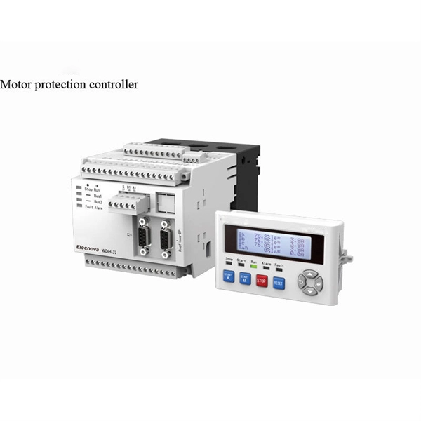
How to Connect Fiber Splitter & Configure ONU with OLT | Onu connected Vsol olt through splitter . more. How to Connect OLT and ONU Devices? To configure the ONU easily, it must first be connected to the OLT. more. The OLT communicates with the optical network unit (ONU) or optical network terminal (ONT) at the user end, coordinating the distribution of data and ensuring that each connected user receives the appropriate information. Equipment Components Generally speaking, OLT equipment includes a rack. FTTH (Fiber To The Home) is a technology that provides high-quality internet access directly to consumers' homes over an optical fiber infrastructure. This provides users with a dependable and high-speed network service and little to no wait times. This network is suitable for building. FTTH (Fiber-to-the-Home): This is a broadband network architecture where optical fiber runs directly to the customer's home, providing extremely high-speed internet, video, and voice services. OLT (Optical Line Terminal): The OLT is located at the service provider's central office or point of.
[PDF]

Network segmentation with switches involves dividing a network into smaller, isolated segments to enhance security, improve performance, and simplify management. Learn how to configure a switch for network segmentation effectively by using VLANs, subnetting, and access control lists (ACLs). You may. to communicate with each other. VLA h or complete physical network. When you physically separate a network, the devic s are assigned to a switch port. However, when a network is separated using VLANs, the devices are logically separated by n of the VLANs is not mandatory. VLANs can also extend. Explore how Versitron single fiber media converters support fiber optic packet forwarding, VLAN tagging, signal amplification, and robust network segmentation—ideal for scalable and secure data infrastructure. Setting up a VLAN on a fiber optic switch is very similar to setting up on any other type of switch, but it's important to make sure the switch supports VLAN functionality. The. By segmenting a network into VLANs, you will increase usable network bandwidth, resources, and performance through the reduction of broadcast traffic. Routers also break up broadcast domains. Routers operate at Layer 3, forwarding packets based on IP addresses, not MAC addresses. A router will. Step-by-step instructions for configuring VLANs using network hardware. Allocate unique segment identifiers directly through your device's interface to minimize broadcast domains and reduce.
[PDF]

ITU & IEC allow 0. 75 dB loss per mated pair. Splitter loss values are "Typical" and include a connector in and out. These values are approximate and should not be exceeded by more than 1-1. 5 dB, which could indicate dirty connectors, bad splices, or. ITU & IEC allow 0. These are known as passive optical splitters, and they perform the function. Let's start with the simplest part: the ideal, theoretical loss caused purely by dividing the light equally among N paths. This is often called Distribution Loss or Ideal Split Loss. Understanding the types of splitters, their impact on network performance, and how to measure their losses ensures high-quality network operation and facilitates optimal splitter selection based on. Use 2×N when two inputs feed the same distribution stage. Common values: 2, 4, 8, 16, 32, 64. Wavelength is recorded in outputs for documentation. 5 dB depending on splitter type. Fusion splices often plan around 0. Optional: patch. Excess loss is the ratio of the optical power launched at the input port of the splitter to the total optical power measured from all output ports. It assures that the total output is never as high as the input. Components, such as fiber cables, splitters, and switches, introduce attenuation. The maximum allowable distance between a transmitting laser and receiver is based upon.
[PDF]
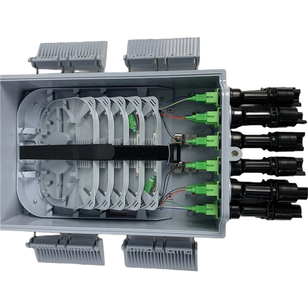
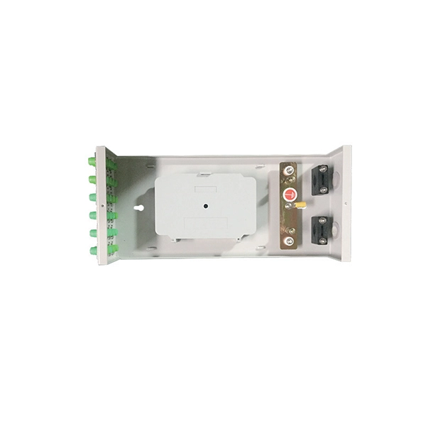
An Optical Splitter (also known as a fiber optic splitter or beam splitter) is a passive optical power management device. “Passive” means it needs no electricity. It requires no power source to work. Imagine a water pipe. One large pipe brings water into a building. Then, smaller pipes split that. A Passive Optical Network (PON) is a fiber-optic access network designed to deliver broadband services. This technology uses fiber cable and unpowered optical components to distribute signals from a central source to multiple end-users. The “passive” designation means the signal distribution points. Optical splitters play an important role in FTTH PON networks where a single optical input is split into multiple output, thus allowing a single PON interface to be shared among many subscribers. The optical splitters have no active electronics and don't require any power to operate. Passive refers to the unpowered condition of the fiber and splitting/combining components. Together, they form the complete infrastructure that makes modern data transmission.
[PDF]