In , a busbar (also bus bar) is a metallic strip or bar, typically housed inside,, and for local high current power distribution, transmission, or switching substations. They are also used to connect high voltage equipment at electrical switchyards, and low-voltage equipment in. They are generally uninsulated, and have sufficient stiffness to be s.
[PDF]
Poland's high voltage oil insulated switchgear market is estimated at USD 145–175 million in 2026, with a compound annual growth rate of 3. 5% through 2035, driven primarily by grid modernization and renewable energy integration. Successful go‑live of day-ahead and intraday capacit. informs that under the Single Day-Ahead Marke. Due to changes in information requirements for the electricity market and Polish Power System Operation a new website containing system data has been launched. Transmission substations account for approximately 55–60% of. The electricity transmission network in Poland is managed by Polskie Sieci Elektroenergetyczne SA (PSE), which is the sole transmission system operator (TSO) in the country. The entire power system in Poland and throughout Europe (excluding the frequency of railway electric traction in Germany and. The ANIA Electrical Centre, operating within the structure of ANIA HOLDING, has been providing comprehensive solutions for the distribution of electrical goods for over 30 years. PSE is the owner of Poland's high voltage electricity grid and is responsible for grid. Polenergia Dystrybucja builds and maintains its own power infrastructure across Poland, through which it distributes and sells electricity. Your browser does not support the video tag. Our clients include shopping malls, office buildings, industrial parks, warehouse centers, housing cooperatives.
[PDF]

Headquartered in Fort Wayne, Indiana, GMS Distribution distributes and sells its products in the United States and Canada. 30 Amp Portable Power Box GMS's Portable Power Distribution Centers have been designed to be the easiest power box you will ever plug in. GMS is focused on the. Our products boast customizable materials and dimensions, ensuring a tailored experience. With a range of materials to choose from and the ability to adjust sizes to your liking, our offerings are designed to meet your unique needs and preferences. American Distribution Boxes are made of high-density polyethylene for years of dependable use. They are non-corrosive, strong, and lightweight for easy handling. Inlet and outlet elevations are positioned to provide equal distribution and meet most local codes. Twist and lock 4” pipe seals and. It is the high-voltage core unit of the American box type transformer, integrating high-voltage load switches, fuses, etc., with a voltage of mostly 15kV. PREMIUM CONSTRUCTION POWER DISTRIBUTION BOX: Crafted by WESTERN, the 6506TLSX Temp power box features a durable blend material for long-lasting performance in demanding environments. ATEK Distribution supplies professional-grade electrical boxes for residential, commercial, industrial, and government projects nationwide. As a certified SDVOSB with 28+ years of experience, we carry every box type you need — correctly specified, fully documented, and ready to ship. Whether you're.
[PDF]
In , a busbar (also bus bar) is a metallic strip or bar, typically housed inside,, and for local high current power distribution, transmission, or switching substations. They are also used to connect high voltage equipment at electrical switchyards, and low-voltage equipment in. They are generally uninsulated, and have sufficient stiffness to be s.
[PDF]
As an essential component of optical fiber communication, optical modules are optoelectronic devices that facilitate the conversion between optical and electrical signals during the transmission process. Operating at the physical layer of the OSI model, optical modules are core devices in optical. The optical module serves as a crucial component in optical fiber communication systems, operating at the physical layer, which is the lowest layer in the OSI model. Classification of Optical Module: Distinguished according to function, package form, transmission rate, wavelength. In the era of 5G, AI, and high-speed data centers, optical modules serve as the core bridge for converting electrical signals to optical signals (and vice versa), enabling fast, reliable data transmission across networks. They are used in fiber optic communication systems to transmit data over long distances with minimal loss and interference. These modules typically consist of a laser or LED transmitter, a.
[PDF]

The solution is to unplug the fiber and reinsert it into the SFP module interface until a “click” sound is heard, indicating the fiber connector and SFP module are properly connected. Contamination or damage on the fiber end face requires the use of a fiber end-face inspection. The physics of noise in optical communication links is of great interest in the design of fiber optic communication systems. The origins of noise in. Optical transceivers—such as SFP, QSFP, and OSFP transceivers —are essential components in high-speed data center and enterprise networks. These fiber optical transceivers convert electrical signals into light and back, enabling long-range, high-bandwidth communication over fiber optic links. Think of it. Optical transmission is vulnerable to various sources of signal degradation, including chromatic dispersion, modal dispersion, polarization mode dispersion, and noise. In the real world, an optical receiver's ability to resolve information is impacted by the presence of noise. They are the foundation of the network world. SFP optical modules are precision devices, and various faults may inevitably occur during operation. These faults can. Noise and Signal Interference in Optical Fiber Transmission Systems is a compendium on specific topics within optical fiber transmission and the optimization process of the system design. It offers comprehensive treatment of noise and intersymbol interference (ISI) components affecting optical.
[PDF]

This guide describes the general requirements, functional and technical performance requirements, test requirements, labeling and packaging requirements, transportation and storage requirements, supply integrity requirements, and quality assurance requirements for hybrid high-voltage. This guide describes the general requirements, functional and technical performance requirements, test requirements, labeling and packaging requirements, transportation and storage requirements, supply integrity requirements, and quality assurance requirements for hybrid high-voltage. Guide for Technical Requirements for Hybrid High-Voltage Direct Current Transmission Protection and Control Equipment This guide describes the general requirements, functional and technical performance requirements, test requirements, labeling and packaging requirements, transportation and storage. purpose of this white paper is to aid WECC members (Specifier) in specifying and applying relay systems that will provide adequate protection of extra-high voltage (EHV) on 345-kV or higher transmission lines and comply with the NERC Reliability Standards. The recommendations in this white paper.
[PDF]

Basic: 300 ft indoor run, standard SC connectors, no trenching. 00/ft, Termination $2. Total: about $2,020; per-foot average around $6. 13 per foot, while a 288-count optical fiber cable for building backbones can reach $6 per foot or more. Pre-terminated assemblies and patch cables incur higher costs due to factory termination, with prices varying by connector type and the number of. The price of fiber optic cabling depends on cable type, length, installation method, and surrounding materials. Typical costs hinge on fiber count, indoor versus outdoor use, and whether trenching, splicing, or termination is required. This guide provides practical ranges in USD and practical price. ⚠️ Note on Units: Prices below are primarily listed Per Meter. We have included Per Foot conversions for reference (1 Meter ≈ 3. Best For. * Disclaimer: Prices fluctuate based on raw material indices (Glass/Copper/Polymer) and cable core count (e. Breakdown of. CRU provides comprehensive, accurate and up-to-date price assessments and research reports for bare optical fibre across various key regional markets, combined with insights into the factors and events affecting markets. Understanding cost and price helps set a realistic budget from the start. Indoor simple run vs armored outdoor, single-mode. Assumes standard jacket; higher if submittal specs require specialty fiber. Higher with high-precision connectors.
[PDF]

They take power from one main source and safely channel it to multiple circuits within electrical enclosures like switchgear, panelboards, and distribution boards, replacing many individual cables. Busbars are fundamental workhorses in power distribution. In electric power distribution, a busbar (also bus bar) is a metallic strip or bar, typically housed inside switchgear, panel boards, and busway enclosures for local high current power distribution, transmission, or switching substations. They are also used to connect high voltage equipment at. Current Rating: Each busbar is rated for a specific current capacity to match system requirements. This setup allows busbars to distribute large currents safely, making them vital in high-power applications. Busbars come in various forms, each suited to different applications depending on the power. Whether it's a high-voltage substation or a low-voltage battery bank, busbars ensure seamless power flow, connecting incoming and outgoing feeders effortlessly. They're not just about distributing electricity; they're about doing it faster, and safer. With modern systems demanding higher efficiency. A busbar is essentially a strip or bar of conductive metal, usually copper or aluminum. In simple terms, a busbar is a common node where multiple incoming and outgoing circuits connect. Typically made from conductive materials like copper, aluminum, or brass, busbars.
[PDF]

Bury cables from 12-36 inches (or 30-90 cm) deep. Where plant life, sidewalks, and other utilities already disrupt earth, it's safer to bury at as little as 24 inches or 60 cm, using protective conduits to limit the likelihood of damaged cables by inexperienced maintenance or. Bury cables from 12-36 inches (or 30-90 cm) deep. These facilities are collectively known as communication infrastructure. Knowing the exact depth of these lines is paramount for anyone planning. The short answer, based on general industry standards and the National Electrical Code (NEC), is that fiber optic cable is typically buried between 24 inches (60 cm) and 30 inches (76 cm) deep. However, simply hitting this depth isn't enough to guarantee your network survives. This. The depth at which cable lines must be buried is governed by a combination of local, state, and national regulations, designed to ensure safety, prevent damage, and maintain infrastructure integrity. These laws typically specify minimum burial depths based on the type of cable (e. 5 meters, balancing protection with installation cost and accessibility. With fiber deployments accelerating in urban and rural areas, understanding these depths is essential for efficient planning and maintenance. In high-load areas such as roads or backbone routes, burial depth can reach 48 inches (120 cm) or more. For broader context on underground.
[PDF]
The price of FRP trays can range from $10 to $50 per meter, depending on the specifications such as size, design, and environmental factors. Cable trays are vital in electrical installations, providing secure pathways for power, communication, and control cables across residential, commercial, and. Using 3/4" conduit for each cable at. 34/ft using 20 ft sections in tray and 10 ft sections for the drop. 21/ea for every 6 ft of cable for the drops and conduit couplers at. Understanding the key factors that influence their pricing helps engineers, contractors, and. This guide covers the critical steps, from selecting the right electrical cable tray and performing accurate cable fill calculations to managing a safe cable pull through and ensuring all bonding and grounding requirements are met. For licensed electricians, mastering these principles is essential. Market context (at-a-glance): Industry analysts valued the global low voltage wire & cable market at roughly USD ~ 145. 7 billion in 2024 and is projected to grow at a CAGR of 7. 2% from 2025 through 2034. Nearly 70% of new homes are now built with low voltage systems (industry estimate) meaning that. Ladder type cable trays are built for heavy-duty routing. In power-heavy areas, they prevent failures that would be far more expensive than the tray itself. Perforated cable trays sit in the middle. They cost less than ladder.
[PDF]
In electric power distribution, a busbar (also bus bar) is a metallic strip or bar, typically housed inside switchgear, panel boards, and busway enclosures for local high current power distribution, transmission, or switching substations. They are also used to connect high voltage equipment at electrical switchyards, and low-voltage equipment in battery banks. They are generally uninsulated, and h. Design and placementThe busbar's material composition and cross-sectional size determine the maximum current it can safely carry. Busbars can have a cross-sectional area of as little as 10 square millimetres (0.016 sq in), but. • – Data transfer channel connecting parts of a computer• – Low resistance electrical conductor for high current transmission and distribution• – Modular approach t. • Elmore, Walter A. (1994). Protective Relaying Theory and Applications. Marcel Dekker.• Paschal, John (2000-10-01). Electrical Construction & Maintenanc.
[PDF]

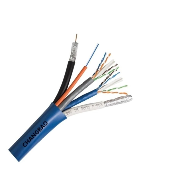
A single strand of glass fiber, called single-mode fiber, is used to transmit single-mode or light beams. It can transmit higher bandwidth than multimode fiber but requires a light source with a limited spectral range. In fiber-optic communication, a single-mode optical fiber, also known as fundamental- or mono-mode, is an optical fiber designed to carry only a single mode of light - the transverse mode. Modes are the possible solutions of the Helmholtz equation for waves, which is obtained by combining. A common type of optical fiber used to transmit over longer distances is single-mode fiber. One of two types of optical fiber, the other is multimode fiber. ” This technology is foundational to modern digital communication, enabling the high-speed transfer of massive amounts of data over vast distances. Generally, single mode cable has a narrow core diameter of 8 to 10µm (micrometers), which can propagate at the wavelength of 1310nm and 1550nm. Modes of light can only propagate through.
[PDF]