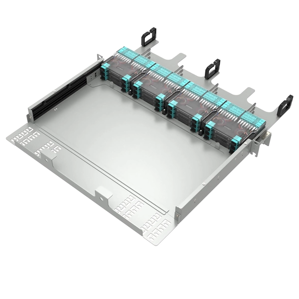
IEC fiber connector standards establish the global specifications for connector geometry, mating interfaces, optical performance classes, and mechanical testing across all fiber network environments. Optical connectors are used to connect optical devices to other optical devices or systems. However, each connection introduces a certain amount of insertion and return loss that. Connectors play an important role in Enterprise network architecture. They give you the power to add, drop, move, and change the network. is a small cylinder used to mount. The Fischer FiberOptic Series offers robust and faultless optical performances in any conditions. Combined with easy use, cleaning and maintenance. Tested for harsh and extreme environments (Norm IEC 61753-1 Cat. These standards ensure that passive fiber-optic components remain interoperable, stable, and. designed for diverse fiber optic applications. But what exactly sets a fibe optic connector apart in terms of its merits? The primary purpose of a fiber optic connector is to terminate the ends of fiber optic cables, ensuring they can be int rconnected reliably with minimal optical loss. After. Fiber optic technology is used in ever-increasing applications due to its inherent advantages (lower weight, EMI/RFI immunity, higher bandwidths and distances) over copper. There are many.
[PDF]

In this paper, various operational factors affecting 100G transmission over G. D fiber-cables are discussed to make the right fiber selection for the long-haul network. Selecting appropriate G. 652 fibre was originally optimized for use in the 1310 nm wavelength region but can also be used in the 1550 nm region. This is the latest revision of a Recommendation that was first created in 1984 and deals with some relatively minor modifications. a number of concatenated cable. G. 92% of. Fiber optic cables are the ultimate technology used in data transfer using light waves. They are classified based on wavelength band, core/cladding size, application, and compliance with international standards such as IEC, ITU-T, and TIE/EIA. In the next sections, the real artwork is putting on. This guide explains the most important ITU-T G. 655—to help you make an informed decision for your project, whether it's a long-haul backbone or a final FTTH drop. In the world of fiber optics, not all glass is created equal. The core of every cable—the optical. Because GPON and XGS-PON are deployed in diverse environments, fiber-containing components such as PLC splitters must be evaluated not only by their standard parameters but also by their sensitivity to bending loss, which is critical for maintaining stable optical transmission. The ITU-T defines.
[PDF]
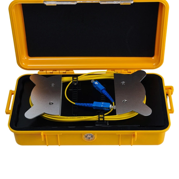
Optical splitters play a crucial role in Fiber to the Home (FTTH) Passive Optical Network (PON) systems, efficiently distributing a single optical signal to multiple destinations. The split ratio and insertion loss are two key parameters defining their performance. Understanding Fiber Optic Splitters: Principles, Parameters, Types, Applications, and Future Trends 1. Introduction Fiber optic splitters are integral components in the world of optical networks. A deeper understanding of these. 📄 What is an Optical Splitter? An Optical Splitter, also known as a beam splitter, is a passive optical device that divides a single input optical signal into two or more output signals. Conversely, it can also combine multiple signals into one. Its primary role is in Passive Optical Networks. Bandwidth is shared amongst customers in a PON, and the bandwidth received by a customer is not related to the power received at the optical network terminal (ONT) as long as the power is high enough so the ONT can operate. Their ability to efficiently manage optical signals makes them indispensable in various. The performance of optical beam splitters can significantly influence the overall performance of laser-based instrumentation and measurement systems. This paper examines two of the most critical performance factors: optical efficiency and wavefront distortion. Efficiency is a function of both the.
[PDF]

The 100FX SFP module for fast Ethernet (FE) ports provides a 100-Mbps optical link using LC connectors and 1310-nm MMF (multimode fiber) cable. The maximum transmission distance for this connection is 2 km. The Cisco 100GBASE Quad Small Form-Factor Pluggable (QSFP) portfolio offers customers a wide variety of high-density and low-power 100 Gigabit Ethernet connectivity options for data center, high-performance computing networks, enterprise core and distribution layers, and service provider. Whether you are maintaining legacy infrastructure or designing industrial Ethernet systems, understanding the technical characteristics of 100BASE-FX SFP modules helps ensure stable and efficient fiber connectivity. 5G SFP Skip to content Search 800G Modules New Arrival! Home Products InfiniBand & Ethernet 800G NDR InfiniBand HOT 400G NDR InfiniBand HOT 200G HDR InfiniBand 100G EDR InfiniBand 56/40G FDR InfiniBand Ethernet Transceiver 25/32/16G Modules 25G SFP28 SR HOT 25G SFP28 LR 25G. OM3 fiber handles 100 meters. OM4 fiber pushes this to 150 meters. OM3 fiber, OM4 fiber, and OM5 fiber support 400G speeds. For a complete listing of hardware compatible with these modules, see the.
[PDF]

This article provides a detailed technical comparison between fiber optic and copper cables, offering a clear perspective for engineers, network architects, and procurement managers. The core distinction between the two technologies lies in the physics of data. However, the exponential growth in data demand has positioned fiber optic technology as the superior alternative for performance, scalability, and future-readiness., 10G/25G/40G/100G and beyond depending on optics and reach). Copper Ethernet scales too, but practical limits are lower and depend. The two main options are fiber optic cables and copper cables, each with its own advantages and drawbacks. Fiber optic cables are praised for their high performance and scalability, while copper cables remain a cost-effective choice, especially for budget-conscious projects and older systems. Copper wire is more susceptible to interference and has limited data capacity, making optical fiber the preferred choice for modern high-speed. Optical connectivity, utilizing fiber-optic technology, has emerged as the superior choice for modern networking, offering unparalleled performance, reliability, and scalability. For example, a typical 10 Gbps copper Ethernet link (such as Cat 6A) over 100 meters can consume approximately 5 to 8+.
[PDF]
Explore the precision, applications, and design principles of beam splitters, essential for advancements in scientific research and technology. Beam splitters are integral optical components that divide a beam of light into two or more separate beams. There are two basic types of beamsplitters: Non-polarizing beamsplitters (NPBS): This type of splitter is used to divide (split) a beam into two beams and each output beam is a fraction of the incoming beam regardless of the polarizations. Non-polarizing beamsplitters are used in a variety of. 📦 For purchasing, use the RP Photonics Buyer's Guide for beam splitters. It provides an expert-curated supplier directory, buyer-focused technical background information, and structured selection criteria to support professional procurement decisions. What are Beam Splitters? A beam splitter (or. As a basic and important link in on-chip photon propagation, beam splitting is of great significance for the efficient utilization of sources and the compact integration of optoelectronic devices. It is widely used in power splitting, polarization separation, wavelength division multiplexing and. The SPIE Digital Library offers a wide range of resources on beam splitters, focusing on their design, applications, and performance across various optical systems. The principle of beam splitting is based on the manipulation of light waves using various optical materials and coatings. Their precision and versatility make them.
[PDF]
This blog article entry considers the merits of choosing which of various low loss RF coaxial cables to use for IoT, LTE or LORA wireless applications where an external antenna is used to connect to router, gateway or terminal. The choice looks deceptively simple—pick a length, screw it on—but RF engineers know the truth: every extra meter quietly eats away at your link budget, especially once you cross 2 GHz. It's not just about length; the cable type, connector quality, and even mounting environment make a measurable. Audio generated by DropInBlog's Blog Voice AI™ may have slight pronunciation nuances. In this article, we will consider cables such as RG174, RG58, RF195. The cheap connectors have inferior dielectric between the poles as well as poorer grades of metal. The dielectric won't handle high power (KW range) as well and the center pin can more easily shift causing impedance problems if they are moved frequently. RF connectors are usually used with coaxial cables. They are designed to maintain the shielding that the coaxial design offers. The better and newer. Besides the wide range of RF connectors, Telegärtner also provides a considerable range of suitable coaxial low loss cables. Using this one-stop shopping option at Telegärtner makes your purchasing process even more efficient. The main use of low loss cables are all kinds of wireless applications.
[PDF]

A consortium of international investors has announced a USD300 million investment to build Guatemala's first fourth-generation artificial intelligence data center, marking a historic step for the country's digital infrastructure. AI (Artificial Intelligence) is the 4th most popular industry and market group. If you're interested in the AI (Artificial Intelligence) market, also check out the top Generative AI, AI Chatbots, AI Virtual Assistants, AI Infrastructure or AI Deployment companies. The project, known as Latam Data Centers Next AI, is being developed. Yesterday, we opened the doors of #ORION, our 27th Data Center in the region. This time in Guatemala. The most sophisticated and advanced Data Center we've built in Latin America with 1mW of power capacity, 1. 6 PUE, 2N / N+1, TIA/EIA 942 and Certified by the Uptime Institute TIER III Certified in. Artificial intelligence is becoming part of everyday life, from how people access information to how public services are delivered. To ensure these technologies are used in ways that benefit people and build public trust, governments need clear guidance, strong coordination, and the right skills. Innovix Solutions brings global expertise to Guatemala City. Cutting-edge AI and machine learning solutions to automate and optimize your business processes. We are the trusted partner for businesses and institutions in Guatemala. Why Choose Us Not Others in Guatemala City? Unlike other providers.
[PDF]
AI servers are high-performance systems specifically designed to process complex AI workloads, including model training and real-time inference. Apple has begun delivering Houston-made AI servers to its data centers nationwide ahead of schedule, a step in scaling its in-ecosystem AI while reshoring some of its manufacturing. They provide the hardware environment —. RedSwitches AI dedicated servers are architected from the ground up to support artificial intelligence workloads. Our infrastructure. At Google Cloud Next '26, we announced that more than 50 Google-managed Model Context Protocol (MCP) servers are generally available or in preview, with more on the way. Why it matters: To move beyond experimental prototypes, AI agents must be able to access real-world data and solve complex. Running AI models on a local AI server is one of the most empowering steps you can take in your AI journey. Instead of depending on cloud APIs, you can bring the intelligence directly onto your own hardware, which unlocks: Improved privacy and security: With locally hosted AI, your data never. Raghav Sethi began his tech writing journey in 2022, contributing to his college's open-source community blog. Later that year, he joined MakeUseOf, and since then has written extensively about Apple, Android, and AI. His work ranges from hands-on experiments to opinion pieces that explore the.
[PDF]

In part one of GIGABYTE Technology's latest Tech Guide, we explore the industry's most advanced cooling solutions so you can evaluate whether your data center can leverage them to get ready for the era of AI. 9 thermal guidelines applied to AI data center cooling — H1 high-density class, B200/GB200 implications, and what's coming in the next revision. Liquid. As Artificial Intelligence (AI) and High-Performance Computing (HPC) workloads drive rack densities beyond 50kW, traditional air cooling is reaching its physical and economic limits. Liquid cooling—specifically Direct-to-Chip (D2C) or Cold Plate technology—has emerged as the standard solution for. Modern AI accelerators have dramatically increasing power requirements, with TDPs rising from 300W (V100) to over 1,400W (MI355X) Heat Output = 700W × 0. 5W thermal BTU/hr = 696. Traditional air-cooling methods are struggling to keep pace with cooling the data center. Compute infrastructures for training large AI models are similar to high-performance computing (HPC) systems, which have long been used for demanding tasks in fields such as engineering, scientific research and finance. Industry insiders familiar with the natural progression of the modern data center will.
[PDF]

Hyperfusion, a leading provider of artificial intelligence (AI) computing solutions, has launched its advanced graphics processing unit (GPU) AI servers in the UAE, aimed at fostering innovation, ensuring security, and shaping the future of AI in the region. Low latency for MENA, Eastern Europe, India and SE Asia inference in H100 GPUs UAE data centres. Deploy production-grade chatbots, customer support agents, and multilingual assistants with a single API call. Stream responses in real time with sub-200ms first-token latency. System prompts. San Francisco, CA & Dubai, UAE – September 30, 2025 – Hyperfusion, the GCC's leading sovereign AI cloud, and CAMB. AI, a global company that enables seamless multilingual communication, today announced a landmark partnership to deliver sovereign, real-time voice AI and agent infrastructure across. Hyperfusion is a leader in high-performance computing and generative AI solutions across the GCC, specialising in secure solutions for AI and ML projects. We only work with the best and global AI leaders to provide cutting-edge cloud compute capabilities tailored to industry needs. Co-founder/CIO. HPC Generative AI Cloud hardware and software solutions. Strategic collaboration combines du's advanced 5G (5G+) connectivity with cutting-edge generative AI technology to transform enterprise video intelligence. The introduction of Hyperfusion's GPU AI.
[PDF]

This qualitative inquiry discusses AI governance in Southeast Asia in the past 5 years and what regulatory policies ASEAN can explore to better modulate its use among its member states. Artificial Intelligence (AI) is a driving force behind ASEAN's ongoing digital transformation. With a rapidly expanding digital economy, AI is projected to contribute between 10% and 18% of the region's GDP by 2030 (Prilliadi, 2025). Among the most disruptive innovations is Generative AI, which. The sixth ASEAN Digital Ministers' Meeting (ADGMIN) held in Hanoi marked a pivotal transition for the region's technical landscape. Under the theme "Adaptive ASEAN: From Connectivity to Connected Intelligence," ministers from the 11 member states—notably including Timor-Leste's historic. onal standards. Recognizing that ASEAN countries are at “different stages of digital development,” the guide is intended to offer ASEAN member states a “flexible” approach to national policies on how to implement, design, develop, and deploy AI systems safely and responsibly, with an eye toward. Only six ASEAN Member States (AMS) have explicit artificial intelligence (AI) strategies, creating regional fragmentation in governance, data protection, and ethical safeguards. It considers the unique political landscape of the region, defined by the adoption of unique norms such as.
[PDF]
The AI Server Market Analysis highlights rapid deployment driven by rising adoption of AI-based workloads such as natural language processing, computer vision, and large-scale data modeling. Market Size by Server, by Hardware, by Cooling Technology, by Deployment, by Application, by End Use. A comprehensive report by Global Market Insights Inc. projects the global AI server market was valued at USD 128 billion in 2024. The market is expected to grow from USD 167. 16 billion by 2030, growing at a CAGR of 38. 7% from 2025 to 2030. Cloud computing and hyperscale data center expansion are driving the AI servers market growth. 73% during the forecast period. The AI Server Market represents a critical backbone of modern artificial. The AI server market is projected to reach USD 837. The growth of the AI server market is driven by the increase in data traffic and need for high computing power. I need the full data tables, segment breakdown, and competitive landscape for detailed regional analysis and. By 2030, AI server sales will grow even further, pushing the market to US$524 billion, representing an 18% Compound Annual Growth Rate (CAGR). Dell, Hewlett-Packard Enterprise (HPE), Inspur, and Lenovo are market leaders.
[PDF]