Explore in-depth fiber laser technical PDFs on repair, upgrades, tuning, maintenance, and DIY projects. Perfect for technicians and enthusiasts. TJS offers complete service and repair programs for many Industrial, Semiconductor, Military, Scientific and Medical lasers including Flash Lamp pumped, Fiber, Diode and CO2 laser technology. Our in-house repair department provides technical support for: H. lamp power supplies, RF-Drivers, PC. Yet for high-value, precision equipment like a fiber laser machine, that mindset is not only outdated but also financially damaging. The leading operators worldwide have already made a key intellectual shift: they recognize that an exceptional maintenance strategy is not a cost—it's a strategic. This guide is designed for maintenance technicians, equipment operators, and facility managers who work with laser systems (e., CO₂ lasers, fiber lasers, solid-state lasers, diode lasers). By implementing these best practices, you can significantly extend the lifespan of your equipment, reduce laser downtime, and ensure every cut is as precise as the last. At. High-performance instruments require proper care to ensure that they work their best to provide you with the best results and allow you to create compelling deliverables, every time. We respect and understand the need for absolute accuracy from the hardware and software our customers use and.
[PDF]

Common methods of protecting busbars include overcurrent-based interlocking schemes, overcurrent-based differential protection, high-impedance differential protection, and percentage differential protection. Interlocking and overcurrent differential protection can be implemented with any suitable. DEFINITIONS. IV EXECUTIVE. Busbar Differential Protection Definition: Busbar differential protection is a scheme that quickly isolates faults by comparing currents entering and leaving the busbar using Kirchoff's current law. Current Differential Protection: This protection method connects CT secondaries in parallel and. Busbars play an important role in power transmission and distribution. They are employed as a central distribution point for all feeders. The problem is that the busbars. Busbars have typically been left without dedicated protection, from the following reasons: It is a fact that the risk of a short circuit happening on modern metal clad equipment is insignificant, but it cannot be completely dismissed. Nevertheless, the damage resulting from one short circuit may be. 25 kV insulation is required. These heat-shrinkable tubes for straight and bent busbars are extremely flexible, allowing them to be easily positioned on busbars and quickly instal ed using a gas torch or oven. They have a high expan-sion ratio, so each size of tubing fits a range of busbar sizes.
[PDF]
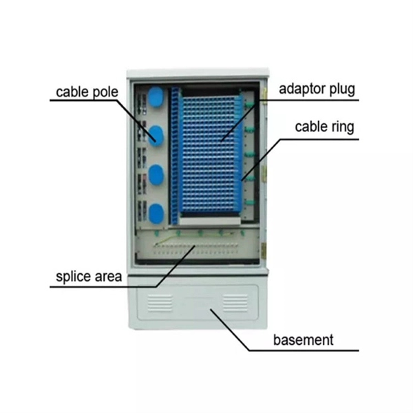
Fiber technicians are taught to keep connections clean after termination, cover connector ferrules and mating adapters with dust caps and clean the ferrule end whenever it is opened to the air. Fiber optic cables are a critical component in modern networks, with their performance directly affecting the stability of data centers and enterprise networks. Effective lifecycle management of fiber optic cables, from selection and installation to daily maintenance and replacement, is essential. That advice is misguided. It could hurt an installer or get them sued by an irate network owner. We've created a simple guide on keeping fiber optic cables in good condition without impairing them. Avoid getting them damaged by handling them with extreme care. We've created a simple guide on maintaining.
[PDF]

Since there are two sections, separated by a circuit breaker, the fault on one section does not interrupt the other section of the bus. Maintenance of the bus section can be done individually, without affecting other. Variants include a sectionalized single bus, where one or more bus couplers divide the bus into segments to limit the extent of outages. Layout: one energized bus; each feeder/generator/transformer bay has a breaker and isolators. Sectionalization adds a bus coupler breaker and isolators to split. The relevant standard for High Voltage Switchboards is 62271-200. This standard covers High Voltage Switchboards with voltage levels above 1kV and up to 52kV. It is also used in small outdoor stations having relatively few outgoing or incoming feeders and lines. shows the single bus-bar system for a typical power station. The generators, outgoing lines and. Bus-bars are copper rods or thin walled tubes and operate at constant voltage. We shall discuss some important Bus Bar Arrangement in Power Station and sub-stations. All the diagrams refer to 3-phase arrangement but are shown in single-phase for simplicity. Single Bus-bar System: The single. This is a single bus system, with additional circuit breaker and isolators, making two different sections of bus, hence called a single bus system with bus sectionalizer. A busbar is a metal bar, usually made of copper or aluminum, that carries electricity inside switchgear.
[PDF]

Perform a dielectric strength test to check the insulation properties of the busbars under high voltage conditions. The Partial Discharge test is crucial for determining long-term part. A busbar protection must be capable of clearing all phase-to-earth faults, and in the case where they can occur, phase-to-phase faults. Policy regarding fault clearance times required from busbar protection varies from utility to utility. Due to the fact that the short-circuit levels of bus bars. Early detection of cracks is crucial for preventing. Check the mechanical. The voltage of the faulted phase decreases (in case of incomplete grounding) or drops to zero (in case of solid grounding). In stable grounding, the. Busbar Differential Protection Definition: Busbar differential protection is a scheme that quickly isolates faults by comparing currents entering and leaving the busbar using Kirchoff's current law. Current Differential Protection: This protection method connects CT secondaries in parallel and. That's based on air insulated buswork well above your head and a reasonable set of remote zone 2 times. I agree with you as chances of surviving a bus fault is practically non existent at 110/220kV regardless if its cleared in ~100ms via busbar prot scheme or via remote end in zone 2 times of.
[PDF]

The PE/PEN combination, comprising busbars, combination angles and baying brackets, supports type-tested configurations to IEC 61 439-1. For assembling 1-pole neutral or PEN conductors. Self-holding nut with knurled ring. Discover the robust selection of secondary pedestals at Hubbell, designed to enhance and secure your power distribution needs. These secondary pedestals are built to withstand harsh environments, ensuring long-lasting reliability and performance. Ideal for a variety of utility applications, they. These bars are tin-plated copper and have stainless steel terminals. Also known as bus bars, they serve as connection points between wires with ring or spade terminals. The underside is sealed, so the bars can be safely mounted to conductive surfaces. Distribution Bar Covers— Distribution bar. Busbars (bus bars) are integral to power distribution and serve numerous industries including automotive, industrial, and aerospace. Busbars are metal bars that can be composed of numerous alloys but are most commonly copper or aluminum. Typical busbar applications include switchgear, panel boards. For attaching the PE/PEN busbar 30 x 5, 30 x 10, 40 x 10 and 80 x 10 mm. With SIRIUS, SENTRON, SIVACON and ALPHA, we offer an innovative portfolio for standard-compliant and demand-oriented applications. Power Busbar System is a modular energy transmission and distribution system created by insulating current carrier Aluminium or Copper busbar conductors placed in a closed body.
[PDF]
Busbars operate as conductive bars that distribute electricity from incoming feeders to outgoing circuits within an electrical system. By providing a low-resistance path, busbars ensure efficient current distribution with minimal power loss. These components are typically mounted within an. Electrical busbars are solid conductors used to carry and distribute high current in switchgear, panels, substations, and power systems. This guide explains how busbars work, common types, key design factors, and how to choose the right busbar for your application. An electrical busbar is a solid. The busbar electrical system performs several essential functions that support efficient power management: Power Distribution: It is a central station to which the electrical power is brought out of one source and to more than one circuit. Existing Transmission: Electric busbar transmits huge. I. Basic Definition of the Small Busbar at the Top of the High-Voltage Cabinet The small busbar at the top of the high-voltage cabinet, as the name suggests, is a small busbar device installed at the top of the high-voltage switchgear. Its primary role is to carry large current loads and connect multiple circuits together. Think. An electrical busbar functions as a metallic conductor, playing a pivotal role as a central link for multiple electrical connections. These connectors can take on various forms including solid, hollow, or even flexible designs to suit different needs.
[PDF]

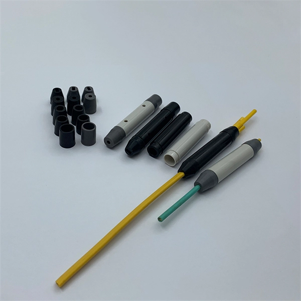
In practice, there are two main ways to terminate fiber optic cable: using a connector to join two fibers to create a temporary, removable joint, or using splicing technology to permanently join two bare fibers directly. Either. Terminating fiber optic cables essentially means putting connectors on fiber optic cable so that you can connect the cable to various devices or network components. Think of it as the equivalent of connecting the dots in a complex puzzle; without proper termination, the whole system can break down. Fiber optic networks are the backbone of modern communication systems, enabling high-speed data transfer and reliable connectivity. When deploying fiber optic cabling, one of the most critical decisions is how to terminate the fiber—either by splicing or using connectors. The process of fiber optic cable termination is the essential act of connecting fiber optic cables to devices, patch panels, or other cables to enable. This Applications Engineering Note explains how different optical fiber termination methods impact the optical performance of telecommunications systems. Optical fiber cabling systems support various communications technologies that use digital as well as analog signaling. This involves either installing a connector or creating a splice to establish a reliable connection point for the optical signal.
[PDF]
This comprehensive handbook will offer a completely updated and revised guide to lasers and laser systems, including the full range of their technical applications. Laser diodes offer high power for their size and produce electrical-power-efficient laser radiation. They consist of a p-n semiconductor junction, with a forward bias voltage applied to trigger a current through the junction. This induces population inversion (of electrons in the excited state) in. A diode laser, also known as a laser diode or semiconductor laser, is a compact electronic device that converts electrical energy directly into coherent light through the process of stimulated emission. The term “laser” is actually an acronym, standing for Light Amplification by Stimulated Emission of Radiation. The first volume outlines the fundamental components of lasers, their properties and working principles, with brand new chapters in. From telecommunications and data storage to medical surgery and 3D sensing, a laser diode is essential for barcode scanners, printers, and industrial cutting. The laser diode is an unsung hero of modern technology. Operational Mechanism: Laser diodes create light through stimulated emission within an optical cavity, with the light's properties influenced by the semiconductor.
[PDF]

These systems work together to achieve the correct balance of temperature, which affects glass viscosity, and draw “tension. ” Other subsystems are instrumental in avoiding vibration and in assuring the bare fiber is not exposed to dust, moisture, and other contaminants. Legal status (The legal status is an assumption and is not a legal conclusion. Google has not performed a legal analysis and makes no representation as to the accuracy of the status listed. ) Current Assignee (The listed assignees may be inaccurate. Two primary processes exist: cold fill and hot fill. Understanding their differences helps manufacturers make informed decisions. Cold Fill: Room Temperature. Optical fibres in a cable are normally protected in one of two ways, either being tight buffered or contained in loose tubes. Fiber is drawn vertically. Step 1: Preparing the Raw Material – Silica The first stage in making a fiber optic cable begins with the raw material: silica (silicon dioxide). Silica is chosen because of its purity and ability to transmit light efficiently with very little loss. The silica is refined and shaped into large. An annealing furnace design has been proposed to lower the attenuation of optical fiber by lowering its fictive temperature during the fiber draw process. The fictive temperature of Germania-doped single mode o fiber lies in the range of 1150~1300 C and this can be tailored by controlling the.
[PDF]
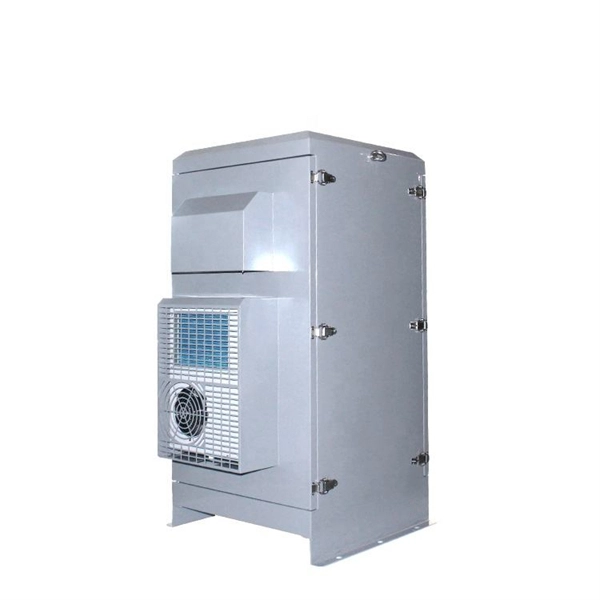
This video shows real on-site footage of electrical installation, demonstrating safe and standardized wiring methods used by professionals. more Learn how to wire a distribution box step by step!. Temporary power systems are essential for construction projects, yet they often introduce serious safety risks. Loose wiring, exposed connectors, and unstable electrical connections can cause shocks, equipment failures, or costly downtime. This article examines how modern portable power cabinet. work requires electrical power for many purposes. However, exposure to weather, frequent relocation, rough use and other condi-tions not normally encountered with conventional wiring systems necessitate special consideration not require in other applications or in completed structures. The. Metal raceways, cable armor, and other metal enclosures for conductors shall be metallically joined together into a continuous electric conductor and shall be so connected to all boxes, fittings, and cabinets as to provide effective electrical continuity. The requirements of Article 590 apply to temporary power and lighting installations and removals, including. Learn what OSHA requires for temporary wiring on construction sites, from grounding and GFCI protection to overhead clearances and employer liability. Temporary wiring on construction sites must comply with the electrical safety standards in 29 CFR 1926, Subpart K. These federal rules, enforced by.
[PDF]
This guide covers the essential tools and step-by-step procedures for low-loss fiber optic cable repair. Fiber optic cables are the backbone of modern networks, delivering fast and reliable data transmission. Accidental cuts, breaks, or other damage can disrupt your network and cause costly downtime. With the right tools and techniques, you can efficiently repair damaged fiber cables and restore. While a cut or damaged fiber optic cable can temporarily take your network down, it is possible to quickly fix the cable with the right tools. This wikiHow article will teach you how to splice a cut fiber optic cable back together with a fiber optic stripper and cutter and a fiber optic crimper. This complete guide covers everything from identifying causes of failure to advanced repair techniques, drawing on the latest industry standards and innovations. Begin by identifying the damage, which can be done using an Optical Time Domain. When fiber cables sustain damage, specialized repair techniques help restore connectivity and maintain data integrity. The actual steps may vary depending on the cable and/or connectors.
[PDF]
A blinking red light on a ZTE WiFi 6 router typically indicates that the router is powered on but isn't receiving an internet signal from the fiber line, or the connection hasn't been fully activated by the provider. First, check the physical connection between the. This guide will walk you through what the LOS light means, why it blinks red and step-by-step instructions on how to resolve the issue, including resetting your router. NSI-79750LW Round Indicator Light with Non Replacable Lamps, Press Fit, 0. 5" Panel Cutout, 0. uxcell 2Pcs Red Green Indicator Light. That blinking red LOS light means your router has lost its connection to your internet provider's network. Before you panic or call tech support, there are several simple fixes you can try at home that often solve this problem in minutes. The LOS light on your router stands for “Loss of Signal. Understanding the possible causes and fixes for this issue is crucial to getting your connection back on track. We will explore common reasons behind the solid red.
[PDF]
