
The transmissive liquid crystal spatial light modulator is composed of an active matrix type liquid crystal board of a thin film transistor (TFT) and its accompanying driving circuit. The LCD board is also integrated with some driving circuits, making the driving method more stable. Spatial light modulator (SLM) is a kind of device that can load information on one-dimensional or two-dimensional optical data field, so as to effectively use the proper velocity, parallelism and interconnection ability of light. It is widely used in the field of modern optical information processing. According to the. The LC 2012 is our basic Spatial Light Modulator system based on a translucent liquid crystal microdisplay with a resolution of 1024 x 768 pixel (XGA). The device is mainly intended for proof of concepts and education. Here, we report on the design and realization of an optically addressable. Spatial light modulators, as dynamic flat-panel optical devices, have witnessed rapid development over the past two decades, concomitant with the advancements in micro- and opto-electronic integration technology. The SLMs are available as single mask configuration for phase or amplitude/polarization modulation.
[PDF]
By spatial filtering we combine four neighboring pixels into one superpixel. At each superpixel we are able to independently modulate the phase and the amplitude of light. We experimentally demonstrate the independent phase and amplitude modulation using this novel. We present a method for full spatial phase and amplitude control of a laser beam using a twisted nematic liquid crystal display combined with a spatial filter. Our SLMs consist of liquid crystal (LC) pixels—each independently addressed—acting as separate electro-optic modulators. The degree of optical spatial coherence—a fundamental property of light that describes the mutual correlations between fluctuating electromagnetic fields—has been proven challenging to control at the micrometer scale.
[PDF]

This section provides an overview for busbars as well as their applications and principles. Here are the top-ranked busbar companies as of May, 2026: 1. Chatsworth. Busbars also known as bus bars, barra electrica, or busbar electrical systems are essential components in modern electrical distribution. Whether used in industrial bus bars, EV charging, renewable energy plants, or building infrastructure, busbars offer compact, efficient, and safe current. High Voltage Busbars are critical components in electrical power systems, designed to conduct high voltage electrical currents efficiently and safely. They are used in substations, switchgear assemblies, and electrical distribution systems to connect different parts of the system and manage the. According to Mordor Intelligence, the busbar market was valued at USD 5. 3 billion in 2023 and is projected to reach USD 7. 5% during the forecast period. What. The global busbar market will expand at a great rate and reach USD 19. 24% between 2023 and 2033. The top companies in busbar market are Siemens AG, Connectivity, Mersen, Schneider Electric, Rogers Corporation, Legrand.
[PDF]
Poland's high voltage oil insulated switchgear market is estimated at USD 145–175 million in 2026, with a compound annual growth rate of 3. 5% through 2035, driven primarily by grid modernization and renewable energy integration. Successful go‑live of day-ahead and intraday capacit. informs that under the Single Day-Ahead Marke. Due to changes in information requirements for the electricity market and Polish Power System Operation a new website containing system data has been launched. Transmission substations account for approximately 55–60% of. The electricity transmission network in Poland is managed by Polskie Sieci Elektroenergetyczne SA (PSE), which is the sole transmission system operator (TSO) in the country. The entire power system in Poland and throughout Europe (excluding the frequency of railway electric traction in Germany and. The ANIA Electrical Centre, operating within the structure of ANIA HOLDING, has been providing comprehensive solutions for the distribution of electrical goods for over 30 years. PSE is the owner of Poland's high voltage electricity grid and is responsible for grid. Polenergia Dystrybucja builds and maintains its own power infrastructure across Poland, through which it distributes and sells electricity. Your browser does not support the video tag. Our clients include shopping malls, office buildings, industrial parks, warehouse centers, housing cooperatives.
[PDF]

12KV High Voltage Epoxy Resin Through Wall Bushing for Busbar TG4-12-140x200 , made from high-quality materials with excellent craftsmanship, customisation available. Please contact us for more information. XBRELE's Epoxy Wall Bushings (also known as Through-Wall Insulators) provide reliable electrical isolation for busbars passing through grounded partitions. Featuring TG3 (KYN28) and Gas-Tight (GIS) series, molded via APG technology for zero partial discharge. Designed for high mechanical bending. Our medium voltage through-wall bushings play a critical role in electrical systems by providing reliable separation between busbars and surrounding components. We design these epoxy bushings specifically for medium voltage applications, ensuring they isolate conductors—such as quarter-inch thick. Our bushings for wall applications are specifically designed to be mounted on the wall or tank of electrical power equipment. 5 is a cast epoxy resin combined bushing busbar wall crossing device used in medium and high voltage power equipment. This equipment is usually used in substations and industrial distribution systems to achieve insulation and sealing functions when cables or busbars pass through walls. Description:Wall busing is a type of electrical equipment used to connect high-voltage cables to devices such as circuit breakers and transformers. Resistant to dirt and moisture, the epoxy.
[PDF]
The first step to finding the right KVM switch is taking inventory of what you'll use it with: specifically, the number of computers, monitors, and additional peripherals, such as a keyboard and mouse. Yo.
[PDF]
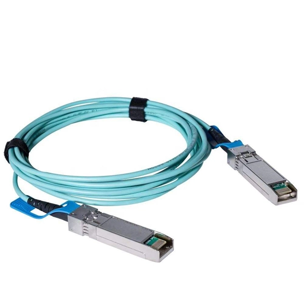
In today's data-driven world, high-speed optical modules (e., 100G/400G/800G) are the backbone of modern networks, enabling ultra-low latency and massive bandwidth for data centers, telecom, and enterprise applications. However, their performance hinges on proper deployment. nd Latency variation are very important in applications requiring accurate timing (e (PAM-4 or Coherent), require complex digital signal processors (DSPs) in optic itional EEPROM data content for propagation del ss C. 2” pluggable : 2% of the cTE budget ITU-T G. 2 allocated for Class C A. 20”. This article helps trading engineers and network architects select an ultra low latency SFP that fits 10G/1G optics needs while minimizing added propagation and serialization delay. A solution for accurately measuring the Latency of PAM4 optical modules is required. Potential source of time error in complex digital parts of pluggables. Higher bit rates (50 Gb/s and higher) and. Transceiver latency is a key spec in enterprise fiber optic networks especially in financial institutions. It is the one of the few variables that can be optimized since fiber path delay is fixed. However, their performance hinges on proper deployment and maintenance.
[PDF]

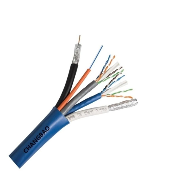
The OMERIN Group is the world's leading manufacturer of cables for extreme conditions (-190°C to +1400°C). Find here High Temperature Cables, High Temperature Wires manufacturers, suppliers & exporters in India. Ideally for a wire to be classified into this category needs to have a temperature rating of 125 degrees C. The High-Temperature Wires can either be a multiconductor or a single conductor. To find out. Established in 1990, Thermo Cables Limited has evolved into a leading manufacturer of specialty cables, serving diverse industries such as Railways, Navy, Defence, Renewable Energy, Nuclear Power, Process Industries, Oil & Gas, and Power sectors. As part of Thermo Group, we are seamlessly. 'Udeytemp' is a specially developed asbestos free insulation material for high temperature use can be insulated on all types of cables covering a vast variety of applications. and. Jiangsu and Zhejiang provinces specialize in industrial-grade cables, hosting facilities like Jiangsu Plaza Premium Electric Instrument and Zhejiang Teflon Wire & Cable with 5,400–6,200 m² production areas. Guangdong's Shenzhen and Dongguan regions focus on high-volume exports, evidenced by. The list above is filled with wholesale jumper wire suppliers, wholesalers, factories, manufacturers (OEM, ODM & OBM), importers, exporters, agents, and more that are certified and verified by Global Sources.
[PDF]
The zero-buoyancy rov cable was born as a power connection and control of underwater robot equipment, as well as signal transmission and feedback link cable applications. The zero-buoyancy cable has been tested by the market and practice due to its excellent. The global underwater zero buoyancy cable market is experiencing robust growth, driven by the expanding offshore energy sector, increasing demand for subsea infrastructure development, and advancements in underwater communication technologies. Linden Photonics is renowned for its innovative fiber-optic solutions, specifically designed for Remote Operated Vehicles (ROVs). These ROV tethers are crucial in underwater applications, offering high performance, durability, and reliability in challenging environments. For use with ROV's (Remote.. Customizable neutral buoyancy fiber optic power cable for ROVs and underwater drones. High‑performance hybrid design combining power and data in one composite cable. Engineered for seawater resistance, flexibility and subsea reliability. Suitable for inspection systems, subsea cameras and. At Invocean, we understand the increasing demands and the critical nature of Remotely Operated Vehicles (ROVs) in various industries such as underwater construction, surveillance, salvage, and scientific research. To support these high-performance tasks, ROVs and Micro-ROV's require reliable.
[PDF]

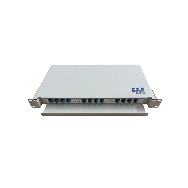
Managing optical attenuation helps keep your signal safe. Clean your optical connectors so you do not lose. Optical Signal Attenuation is the single greatest factor limiting the distance and performance of your network. Understanding it is crucial for anyone involved in data centers, telecommunications, or enterprise networking. This guide will demystify signal loss, explore its causes, and show you how. In high-speed environments, where the optical link budget is measured in fractions of a decibel, diagnosing and eliminating unexpected loss is the network engineer's most critical task. This field guide provides a systematic, step-by-step approach to troubleshooting and resolving the most common. Signal loss in Fiber Optic networks can make data slow. It can also break your connection. You should fix it fast to get speed and stability back. > You can solve this with simple steps. Signal Degradation (Loss of Light) When the signal quality degrades, it could be a sign of attenuation or excessive loss in the system. The signal might become weaker, resulting in slower speeds or dropped connections. -. Fiber optic networks are celebrated for their speed and reliability, but even the best systems can encounter problems. When issues like signal loss, slow speeds, or intermittent connectivity arise, systematic troubleshooting is key. Things like impurities in the fiber core and reflections at the core-cladding edge cause this drop.
[PDF]
Monochromatic light sources give the best performance with cube beamsplitters. A plate beamsplitter would be a better option if the light source is a high-power laser, as the laser light will produce less internal heat. Another factor to consider is the packaging. A beam splitter or beamsplitter is an optical device that splits a beam of light into a transmitted and a reflected beam. It is a crucial part of many optical experimental and measurement systems, such as interferometers, also finding widespread application in fibre optic telecommunications. It provides an expert-curated supplier directory, buyer-focused technical background information, and structured selection criteria to support professional procurement decisions. Beamsplitters are often classified according to their construction: cube or plate. These optical components divide incident light into two distinct beams: one reflected and one transmitted. This precise ability to direct light paths makes beam splitters essential in various applications, including imaging systems, laser systems, and telecommunications. The splitter transmits one part while reflecting the other. These exiting beams are differentiated by either their optical power (non-polarizing) or polarization states (polarizing). Non-polarizing beamsplitters are specified by their splitting ratio, i.
[PDF]

This GAOTek Multi-Wavelength Optical Light Source is a portable device which provides a single button switch operation for the following multi-wavelength output options: 650 nm, 850 nm, 1300 nm, 1310 nm and 1550 nm. This product is already in your quote request list. Overview. Unlock exceptional illumination versatility with the Prizmatix CombiLED high-power multi-wavelength LED illuminator engineered for microscopy and a wide range of scientific applications that demand intense, precisely controlled light across multiple discrete wavelengths. The CombiLED Light Engine. For nearly 30 years, RPMC's selection of Multi-Wavelength Lasers has set the standard for affordable precision across a wide range of applications, from defense to medical, industrial, and research with 1000's of successful units in the field. We understand that every application has unique. Multiple LED sources can be efficiently combined into a single output beam, and offer major advantages such as long life-time, easily tunable spectrum, high power stability, and ultra-fast switching (on the microseconds level) without using moving mechanical components. Multi-Wavelength Collimated. Sirchie provides the industry's best multi-wavelength forensic alternate light sources to the global law enforcement community. They provide a more complete range of wavelengths to cover more of the UV to IR spectrum for many application areas The CS-16-500W CrimeScope was designed for those.
[PDF]

A lighting control module operates as the central controller for a lighting system. It receives input from switches, apps, or sensors and regulates electrical flow to connected lights. Depending on the setup, it adjusts brightness, color temperature, or full lighting scenes. It acts as a bridge between your physical lighting fixtures and the smart systems that manage them. Instead of relying solely on traditional wall switches, you can control your lights via remotes, mobile or web apps. A lighting control module is an essential component in a lighting control system that manages how lights are powered, dimmed, or switched on and off. Think of it as the “brain” that receives commands—either from a manual switch, a sensor, or a building automation system—and translates them into. A lighting control module is a smart device that manages lighting circuits, adjusting brightness, automating schedules, and responding to sensors. It enhances comfort, efficiency, and ambience in homes and commercial spaces. Explore the multifaceted benefits and applications of lighting control modules, from home automation to industrial. These modules are designed to communicate with various sensors, switches, and control panels, making lighting adaptable to different environments and user preferences. It enables precise management of lighting systems, allowing for adjustments in brightness, color, timing, and even integration with other smart devices. This innovation.
[PDF]

