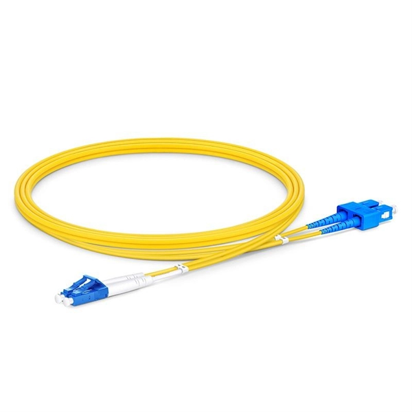
Mainly 9steps: Step 1: cut cable with cutting machines in lengths Step 2: put the connector spare parts on the cable Step 3: Strip cable jacket, coating till bare fiber, and make all parts in ready Step 4: Insert fiber into ferrule, glue dispenser and heat oven Step 5:. Mainly 9steps: Step 1: cut cable with cutting machines in lengths Step 2: put the connector spare parts on the cable Step 3: Strip cable jacket, coating till bare fiber, and make all parts in ready Step 4: Insert fiber into ferrule, glue dispenser and heat oven Step 5:. Learn how to make a fiber optic patch cord step by step, from preparation to testing, for reliable high-performance connections. Most guides on making fiber optic patch cord 1 s feel incomplete. They often focus on the final assembly steps, leaving the foundational stages a mystery. From cable cutting to connector assembly and testing, you will gain valuable insights into the production of. Fiber optic patch cords and Pigtails are very important passive fiber optic components in fiber optic networks. Use the fiber optic cleaver to cut the. This document describes the installation and use of the mode-conditioning patch cords listed in Table 1. A mode-conditioning patch cord is shown in Figure 1 IEEE 802. 3z-compliant optical fiber assembly consisting of a single-mode fiber permanently coupled off-center to a 62. 5-micron multimode.
[PDF]
This comprehensive guide will delve into the best practices for cable removal, the benefits of maintaining a clean cable environment, and step-by-step instructions to ensure the process is efficient and compliant with industry standards. Every new installation means an increased number of low voltage cables that are cut and left in ceilings, floors, and walls. From a tenant or building owner's point of view, removing abandoned cable has. Effective cable removal ensures safety, optimizes performance, and prepares the infrastructure for future upgrades. Before beginning any installation, safety. Fiber-optic cables are the backbone of modern connectivity—powering 5G networks, global internet backbones, and data center interconnections with near-light-speed data transmission. While these cables are engineered for durability (with some rated to last 25+ years), they are not invulnerable. Even. Here are 5 vital rules for staying safe when you're working on fiber optic cables. Know the standards that apply to your work Whether you're installing new fiber optic cables or troubleshooting and repairing an existing fiber network, a working knowledge of the regulations that apply to your. In outside plant fiber optic installations, the biggest cause of network failure is likely to be electronic problems or, if it's in the cable plant, what is usually called “backhoe fade” for buried cables and “target practice” for aerial cables, both of which are self-explanatory.
[PDF]

Traditional turbidity monitoring methods involve the manual collection of water samples at set locations and times followed by laboratory analysis, which are labor intensive and time consuming. Fiber-optic measurement permits real-time, in situ turbidity monitoring. But the current technology is. This paper presents the development of an optical fiber sensor system for multiparametric assessment of temperature and turbidity in liquid samples. The sensors are based on the combination between fiber Bragg gratings (FBGs), intensity variation and surface plasmon resonance (SPR) sensors. Electrical, Electronic and Communication Engineering Dept. ; bFiber Photonics Department, UMR CNRS/University of Limoges 7252, 123 Avenue Albert Thomas, 87060 Limoges cedex, France; c“Grupo de Ingeniería fotónica”, Avenida Los Castr s. Turbidity is caused by the presence of suspended particles, organic matter, and chemicals, and is widely measured in natural resources, irrigation water, the food and beverage industry, and drinking water [1,2,3]. As an important water quality parameter, turbidity not only indicates the efficiency. Create a new folder below. Sensors were designed in two versions: for examination of liquid samples and for monitoring of transparency in the flow of liquids ('on-line'.
[PDF]
The three primary types of fiber optic cable are single-mode fiber (SMF), multimode fiber (MMF), and plastic optical fiber (POF), each designed for specific applications based on distance, bandwidth, and cost considerations. Fiber optic cables transmit data as light, enabling faster and more reliable communication than traditional copper wires. Unlike copper wires, which are limited by lower data transmission speeds, shorter transmission distances, and higher susceptibility to electromagnetic interference, fiber optic cables offer unparalleled performance and can. While copper-based solutions (such as Cat5e/Cat6 for twisted pair or RG-6 for coaxial) have long served as workhorses for local and broadcast networks, fiber optic cable have seen explosive growth over the last decade. You'll learn what sets these cables apart, when to use each type, and how to avoid common installation mistakes. Whether you're. There are three main types of fiber optic cable. These are single-mode, multimode, and plastic optical fiber. Each type is good for different uses. Single-mode fiber sends data far away. The choice of fiber optic cable depends on the specific needs of the application, as well as the.
[PDF]
Splicing allows you to restore or expand fiber networks while maintaining signal integrity. When done right, splicing ensures minimal loss and long-lasting performance. This is where fiber optic cable splicing—the process of creating a permanent, high-performance join between two fiber ends—becomes critical. For network managers and technicians, a poor splice can lead to significant signal degradation, network downtime, and costly troubleshooting. At Turn-Key. To begin, the standard definition of splicing in optical fiber is joining two fiber optic cables together. The other, more common, method of joining fibers is called termination or connectorization. Splicing is most commonly used in the field but has application in cable assembly houses. Whether repairing a broken cable or extending a fiber run, fiber optic splicing ensures light signals travel. Whether you're installing new cables or repairing damaged ones, splicing techniques play a vital role in maintaining signal integrity. Choosing the right method affects performance, cost, and long-term durability. In this blog, we'll explore the main types of fiber optic splicing techniques, their. Joining two optical fibers at the right place so that light can be transmitted through them with minimal loss and reflection is known as splicing. Fiber optic splicing is done through two main methods. In fusion splicing, the ends of the fibers are welded together with heat. This guide will walk you.
[PDF]
Long Expansion Cycle: Optical fiber preform production has high technological barriers, and the expansion cycle can take as long as 18-24 months. Even if manufacturers start expanding immediately, the new capacity will not be available until at least 2027. This phenomenon is the result of multiple factors, including tight supply of optical fiber preforms (preforms), long expansion cycles for optical fiber production capacity, and the explosive growth of emerging applications such as AI computing power and drones. The expansion cycle of optical fibers is generally less than 6 months, and fiber optic cables can take 3 months. The expansion of production requires the purchase of equipment and the construction of factories. At the heart of this transformation lies fiber optic cable manufacturing, a precise and sophisticated process that powers our interconnected world. With the global fiber optic market reaching $6 billion and growing at 10% annually, the need for high-quality manufacturing solutions has never been. The manufacturing process of fiber optic cables involves several intricate steps that culminate in the production of high-performance data transmission solutions. This process begins with the creation of a preform, which serves as the foundation for the optical fibers within the cable. This intricate process combines cutting-edge technology, precise engineering, and.
[PDF]
The cost to install fiber optic cable ranges from $1. 50 to $42 per foot, with installation costs accounting for 60-80% of total project expenses. According to the Fiber Broadband Association's 2025 report, median costs are $8 per foot for aerial builds and $18 per foot for. Fiber optic cable installation costs between $1,500 and $7,000 for your home, with prices varying by cable length and installation method. The installation type you choose and the layout of your property determine the total labor and materials needed for your project. You should account for permit. The initial cost of installing fiber optic cables can vary depending on the chosen installation method and specific project requirements. Total Project Costs: For commercial installations, expect costs ranging from $5,000 to $20,000 per mile for underground projects and from $40,000 to $60,000 per. Homeowners and businesses typically pay for fiber optic cable installation based on distance, conduit needs, and labor. The main cost drivers include material type, run length, trenching or aerial work, and any required permits or inspections. This comprehensive guide breaks down the factors influencing pricing, average expenses, and tips to get the best value in 2025. Clear insights help make informed decisions without unexpected surprises. Let's start by getting a better idea about the material cost. Understanding the fiber cable cost per foot is crucial before.
[PDF]
Single mode and multimode fiber optic cables are two different types of fiber optic cable aimed at different use cases. Single mode cables are typically made with a single strand of glass at their core, leading to a n.
[PDF]

The fiber optics market is experiencing robust growth, propelled by the rising demand for high-speed communication networks, expanding internet penetration, and the rapid adoption of cloud services and data-intensive applications. The " United States High Density Fiber Optic Cables market " has witnessed significant growth in recent years, and this trend is expected to continue in the foreseeable future. Introduction to United States High Density Fiber Optic Cables Market Insights The United States High Density Fiber Optic. The fiber optics market is projected to grow from USD 9. 7 billion in 2025 to USD 24. Glass fibers will dominate with a 57. 2% market share, while single-mode will lead the cable type segment with a 63. At the same time, the supply chain supporting fiber deployment faces new challenges that require a coordinated response from all. Fiber optic cable market has emerged as vital part of the worldwide telecommunications and data transmission system. The market size, estimated at $50 billion in 2025, is projected to expand. Fiber optic cable is a cable containing one or more optical fibers that are used to carry light signals over long distances with minimal loss. These cables consist of glass or plastic fibers that transmit data through pulses of light, offering significantly higher bandwidth and faster transmission.
[PDF]

The OPPC cable (Fiber Optic Composite Aerial Phase Conductor) is an innovative optical cable that integrates electrical power transmission and optical fiber communication. By incorporating fiber optic units inside the phase conductor, it ensures both energy transmission and. Electrical utilities have networks used to transmit and distribute electrical power over a large geographic area. In their served areas will be power generating stations, alternative energy sources (solar, wind, geotherman, etc. ), substations for distribution and microgrids. These networks must be. wer transmission systems. The cable is used in power transmission lines, due to its excellent performance in low and medium-voltage electrical networks. This article will provide some knowledge of OPPC cable. What is OPPC. Optical Phase Conductor (OPPC) is used as an alternative telecommunications solution when there is no existing ground wire, meaning Optical Ground Wire (OPGW) is not a viable option. It combines optical fiber technology with traditional conductors, enabling real-time monitoring, improved performance, and increased reliability of.
[PDF]

This cabling system organizes and manages fiber optic cables and copper cables through cable trays, patch panels, and structured cabling systems, enabling easy maintenance and scalability. Fiber and Cat6a can run together in shared trays when properly separated. Protect the fiber bend radius at all transition points. Avoid stacking heavy copper bundles on delicate fiber. Separate power cables from data cabling. Prevent tray overcrowding to maintain airflow. Wire mesh trays enhance. Data center cabling refers to the organized system of cables and related infrastructure to connect and manage the various components within a data center. This system ensures efficient data transmission and reliable connectivity in a data center environment. Structured cabling is a methodical. As data centers continue to grow in complexity and scale, efficient fiber optic cabling is essential for maintaining high performance, reliability, and scalability. Cabling not only supports current performance but also ensures future adaptability. Proper planning and implementation of cabling infrastructure can significantly reduce downtime, improve airflow, and ensure.
[PDF]

This helps keep fiber optic cables safe from harm and signal problems when you put them in. Use the right lubricant. Follow the rules for tension and bend radius. Try new methods like air blowing. Use smart. Fiber optic cable is strong, reliable and built for long-term performance, but it still needs to be handled correctly during installation. This article explores recommendations for pulling and installing fiber optic cable. Most fiber optic cables boast a pull strength of 100 – 200. Fiber optic cable and copper twisted-pair cable may seem alike at first glance. Both types come in a coil or on a reel and are typically installed in the same areas with similar tools and techniques. Yet the materials differ greatly. A copper wire can take a twist with little worry, but glass. Installing fiber optic cable requires precision, skill, and a commitment to safety, especially when using powerful underground cable pullers. While these tools boost efficiency, their complexity introduces risks that demand proactive management. This guide provides a comprehensive overview of. When deploying fiber links in data centers, LANs, or even in outside plant networks, fiber is pulled between equipment and spaces through pathways, cable managers, cable tray, risers, or conduit. This makes sure the cable pull is smooth and safe. Use smart monitoring devices.
[PDF]
An optical module sends data as light through fiber cables. Light is faster than electricity, making it great for quick communication. The optical module serves as a crucial component in optical fiber communication systems, operating at the physical layer, which is the lowest layer in the OSI model. Its primary function is to achieve optoelectronic conversion by converting electrical signals into optical signals and vice versa. This technology is crucial for fast and reliable data transfer in networks. Optical modules typically have an electrical interface on the side that connects to the inside of the system and an optical interface on the side that connects to the outside. Optical fiber transmission forms the backbone of modern high-speed communication networks, enabling the efficient transfer of massive datasets across vast distances. These modules typically consist of a transmitter, which converts electrical signals into a light signal, and a receiver, which converts the received signal back. In high-speed data networks, the seamless integration of fiber optic cables with SFP (Small Form-Factor Pluggable) modules is critical for reliable signal transmission. SFP transceivers bridge electrical and optical signals, making them indispensable in data centers, telecom networks, and.
[PDF]