For most setups, cables with 12, 24, or 48 cores are common choices, ensuring compatibility with modern equipment and ease of management. Fiber cores are the heart of fiber optic cables, transmitting light signals that carry data. Made from either high-quality glass or plastic, the core plays a critical role in determining the cable's performance. The total number of cores for a 1pc fiber patch cable is calculated as the number of. In fiber optic cables, data is transmitted as pulses of light that travel along a thin strand of glass or plastic fiber. The light is typically. The number of optical cores in an optical fiber is the total number of equipment interfaces multiplied by 2, plus 10% to 20% of the spare quantity, and if the communication mode of the equipment has serial communication and equipment multiplexing, you can reduce the number of cores. The following ZR Cable introduces some methods to determine the number of fiber cores. First of all, clearly know the number of wiring points in this layer, calculate the number of switches, and whether the connections. A fiber-optic cable, also known as an optical-fiber cable, is an assembly similar to an electrical cable but containing one or more optical fibers that are used to carry light. ” However, when light enters the core it needs to remain within it, and one layer that ensures that is called.
[PDF]

A lighting control module operates as the central controller for a lighting system. It receives input from switches, apps, or sensors and regulates electrical flow to connected lights. Depending on the setup, it adjusts brightness, color temperature, or full lighting scenes. It acts as a bridge between your physical lighting fixtures and the smart systems that manage them. Instead of relying solely on traditional wall switches, you can control your lights via remotes, mobile or web apps. A lighting control module is an essential component in a lighting control system that manages how lights are powered, dimmed, or switched on and off. Think of it as the “brain” that receives commands—either from a manual switch, a sensor, or a building automation system—and translates them into. A lighting control module is a smart device that manages lighting circuits, adjusting brightness, automating schedules, and responding to sensors. It enhances comfort, efficiency, and ambience in homes and commercial spaces. Explore the multifaceted benefits and applications of lighting control modules, from home automation to industrial. These modules are designed to communicate with various sensors, switches, and control panels, making lighting adaptable to different environments and user preferences. It enables precise management of lighting systems, allowing for adjustments in brightness, color, timing, and even integration with other smart devices. This innovation.
[PDF]

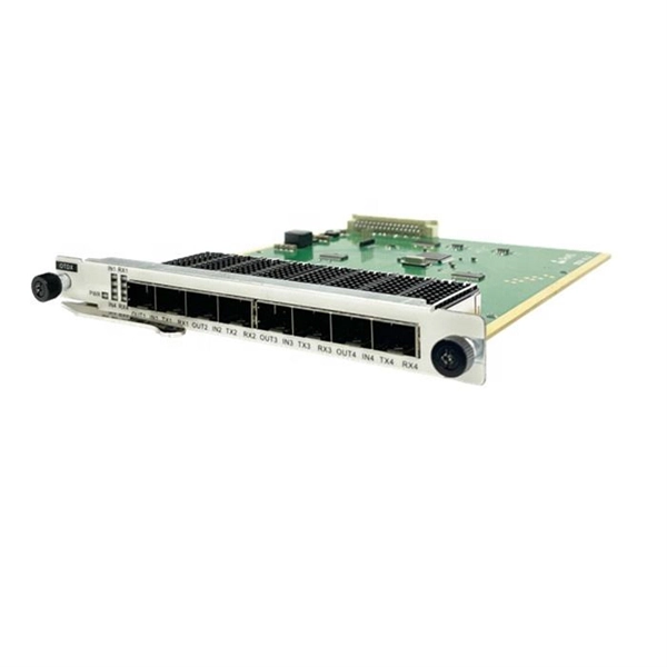
These data switches are responsible for routing and data switching at the core layer of the network. The data routed and switched by the core switch is carried forward to the bottom layers of the network such as the distribution and access layer. Engineered to aggregate massive volumes of data from distribution switches, it provides ultra-low latency and maximum throughput to ensure uninterrupted routing and packet. The significance of the core switch in building and sustaining a resilient network infrastructure is paramount. This determines network efficacy, dependability, and the speed at which. There are different types of enterprise switches that perform various roles in these layer-based or hierarchical ethernet networks. The hierarchy Ethernet network. A core switch in networking serves as the high-capacity backbone, italic centralizing data flow and ensuring efficient communication between different network segments. Simply put, it's the kingpin that keeps your network humming. You may also want to know: Can a Nintendo Switch Play DS Games? ·. A core switch is the backbone of a large-scale network, designed to handle massive volumes of traffic with ultra-low latency and maximum reliability.
[PDF]

The optical fiber cold joint is used when two pigtails are docked. The main part inside it is a precise V-shaped groove. It is used to connect optical fiber or optical fiber butt pigtail, which is equivalent to making a joint (fiber butt pigtail refers to the butt joint of the fiber core of the optical fiber and the pigtail instead of the pigtail head mentioned in the former), and is used for this kind of cold. When installing a fiber optic network, connectors are required to connect both ends of the fiber optic cable. Common splicing methods include optical fiber cold splicing and optical cable hot fusion splicing. Advantages and disadvantages of fiber optic cold splicing Fiber cold splicing refers to. Mechanical splicing involves physically aligning and holding two fiber ends together using mechanical means. This method is typically used for permanent connections, but it allows for disassembly without damaging the fiber ends. Mechanical splices are often preferred for their simplicity and. Optical fiber transmission offers numerous advantages, including a wide frequency bandwidth, high communication capacity, low signal loss, immunity to electromagnetic interference, compact cable size, and the availability of abundant raw materials. As a result, it has become a preferred medium for. Executive Summary: A fiber optic pigtail is one of the most commonly specified yet least understood components in structured cabling.
[PDF]

More specifically, these systems keep tabs on voltage, current, and temperature limits and control the disconnect relay. This allows them to disconnect themselves from the external application in case of malfunction. From a drop of rain to the shining sea, an energy storage system is like the earth's bodies of water (hear us out). In a battery energy storage system (BESS), the energy in the battery cells is like raindrops that combine to form a brook. Made of the combined energy from cells, these brooks combine. Battery energy storage systems (BESSs) investment is expected to grow to $103 billion by 2030. ) Battery systems aren't just designed to serve as local power backups, such as the systems used to power critical facilities (including hospitals and data centers) when the normal. When a 300 MWh battery energy storage system (BESS) in Arizona tripped offline during July's heatwave, operators discovered voltage fluctuations had overwhelmed its protection relays. Could your facility withstand such stress? As global BESS installations surge—projected to reach 1. Protection is necessary when energy and voltages combine from the modules, as well as from the battery racks. Fuses are an efficient. The electrical integration design of a Battery Energy Storage System (BESS) is based on the application scenario and includes various aspects such as DC, high/low voltage distribution, control power distribution, grounding, lightning protection, and safety standards.
[PDF]

The document discusses optical detectors used in fiber optic communications systems. It describes the functioning of PIN photodetectors and avalanche photodetectors (APDs). Their performance. An optital detector is a device that converts light signals into electrical signals, which can then be amplified and processed. Such detectors are one of the most important components of an optical fiber communcation system and dictate the performance of a fiber optic communication link. PIN Photodiode A PIN photodiode is a widely. Detectors perform the opposite function of light emitters. The most common detector is the semiconductor photodiode, which produces current in response to. It explains how these devices use optical fibers to measure quantities like temperature, mechanical strain, pressure, and vibrations by detecting changes in light propagating through the fiber. A central focus is on sensors based on fiber Bragg gratings, where the Bragg wavelength is sensitive to. Optical Power Meters: These devices measure the power of optical signals in fiber optic cables. This information helps in maintaining signal integrity and quality across the.
[PDF]

Over the past few decades, silicon-based solar cells have been used in the photovoltaic (PV) industry because of the abundance of silicon material and the mature fabrication process. Department of Energy (DOE) Solar Energy Technologies Office (SETO) supports crystalline silicon photovoltaic (PV) research and development efforts that lead to market-ready technologies. Below is a summary of how a silicon solar module is made, recent advances in cell design, and the. Silicon solar cells are the dominant technology in the global renewable energy transition, accounting for over 95% of the photovoltaic (PV) market share. Decades of engineering refinement have transformed this once expensive space technology into the most cost-effective source of new electricity. Photovoltaic (PV) installations have experienced significant growth in the past 20 years. During this period, the solar industry has witnessed technological advances, cost reductions, and increased awareness of renewable energy's benefits. Research activities at ISFH in the field of silicon. In the topic "Silicon Solar Cells and Modules", we support silicon photovoltaics along the entire value chain with the aim of bringing sustainable, efficient and cost-effective solar cells and modules to industrial maturity. However, as more electrical devices with wearable and portable functions are required, silicon-based PV solar cells.
[PDF]

Precision begins with a quality optical encoder disc in the automation, robotics, and motion control systems of today. This tiny yet essential device transforms physical movement into exact digital signals that dictate speed, position, and direction. What constitutes an optical transceiver? An optical transceiver, a crucial device utilized in optical communication, is an optoelectronic element, allowing the interconversion of optical and electrical signals during the information transmission. It generally has the components for transmission. Therefore, NASA is developing optical communications to address limitations of radio frequency (RF) communications, including: bandwidth, spectrum and overall size of frequency packages and power used. Optical spectrum uses light as a means of transmitting information via lasers. Optical. Optical transceivers are devices that convert electrical signals into optical signals and vice versa, playing a key role in supporting modern high-speed communication networks. They are widely used in data centers and communication systems to enable high-speed, efficient transmission of large. Optical transceiver modules are designed and built by a variety of manufacturers. In the design of optical transceivers, the selection of channel configuration and modulation.
[PDF]
Light sources are devices that generate the optical signals transmitted through fiber optic cables. In fiber communication, the most commonly used light sources are LEDs (Light Emitting Diodes) and laser diodes. LEDs are used in short-distance, low-speed systems due to their broader spectral width. Optical fiber primarily uses infrared light, not visible light, due to lower signal attenuation. Common wavelengths are 1310nm and 1550nm, where silica glass fiber has minimal loss (as low as 0. Lasers or LEDs generate the light, which carries data through total internal reflection within. Most systems use a "transceiver" which includes both transmission and receiver in a single module. The transmitter takes an electrical input and converts it to an optical output from a laser diode or LED. It often uses glass or plastic cables, which address the problems of traditional copper cables' poor speed and limited distance bandwidth carrying. VCSEL (Vertical Cavity Surface Emitting Laser)- VCSELs (pronounced 'vixel') emerged in the 80's as a new kind of semi-conductor laser and were soon recognized for their potential in fiber optics. When Gigabit Ethernet products were developed LEDs could not modulate (turn on and off) at required.
[PDF]

Fiber optic cable pole brackets and hooks refer to the equipment used for mounting and securing fiber optic cables on utility poles or other vertical structures. (FOA) was founded in 1995 to help develop the workforce to build the fiber optic networks to support a rapid expansion in communications and the Internet. The charter of the FOA was to promote professionalism in fiber optics through education, certification, and. Indoor fiber optic cable uses tighter buffers and routes through conduits or trays. Outdoor fiber optic cable has rugged jackets, gel-filled or water-blocking layers, and armor to resist moisture, rodents, and temperature swings. You install indoor cables in controlled environments. Outdoor fiber. 4. FO-VC2 JOINT USE - VERICAL MIDSPAN CLEARANCES 48. FO-GB GROUNDING AND BONDING 49. FO-RI JOINT USE RISER. Our Fiber Optic Mounting Hardware category includes essential components designed to secure, organize, and protect fiber optic cables and equipment. Proper mounting hardware is crucial for efficient cable management, strain relief, and long-term network stability. However, installing fiber cables in outdoor environments exposes them to harsh weather conditions such as rain, thunderstorms, and freezing temperatures.
[PDF]
Multi-mode optical fiber is a type of mostly used for communication over short distances, such as within a building or on a campus. Multi-mode links can be used for data rates up to 800 Gbit/s. Multi-mode fiber has a fairly large core diameter that enables multiple light to be propagated and limits the maximum length of a transmission link because of. The standard defines the mos.
[PDF]

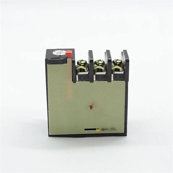
In this video, I'll show you how to build a simple and effective short circuit protection circuit using a relay. This DIY project is perfect for anyone looking to protect their electronics from accidental shorts. Last Updated on February 15, 2026 by Swagatam 117 Comments In this post I will try to explain the making of a simple 220 V, 120 V AC mains short circuit breaker using an SCR and a triac combination, (researched and designed by me). The circuit is an electronic version of the normal main circuit. One possible solution to the problem of overcurrent is to use a variable bench power supply with a current limit function. These power supplies allow You to set a current limit, preventing a high current flow when a mistake occurs. This circuit will. Why Publish? How to Make Short Circuit Protection Circuit: Hii friend, Today I am going to make a circuit for Short Circuit protection. This circuit we will make using 12V Relay. How this circuit will Work - when short circuit will occur on the load side then the circuit will be automatically cut o. In this tutorial, we will see how to make a short circuit protection using Relay. Many times accidentally terminals of batteries and other power supplies get short-circuited. Due to this, they get hot and start degrading. In the case of lithium-ion or lithium-polymer batteries, they may catch fire.
[PDF]
Fibre Channel switches can be divided into two classes. These classes are not part of the standard, and the classification of every switch is a marketing decision of the manufacturer: Directors offer a high port-count in a modular (slot-based) chassis with no single point of failure (high availability).Switches are typically smaller, fixed-configuration (sometimes semi-modular), less redundant devices. OverviewFibre Channel (FC) is a high-speed data transfer protocol providing in-order, lossless delivery of raw block data. Fibre Channel is primarily used to connect to in (SAN) in co. When the technology was originally devised, it ran over optical fiber cables only and, as such, was called "Fiber Channel". Later, the ability to run over copper cabling was added to the specification. In order to avoid confu.
[PDF]