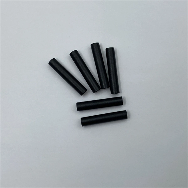
Mainly 9steps: Step 1: cut cable with cutting machines in lengths Step 2: put the connector spare parts on the cable Step 3: Strip cable jacket, coating till bare fiber, and make all parts in ready Step 4: Insert fiber into ferrule, glue dispenser and heat oven Step 5:. Mainly 9steps: Step 1: cut cable with cutting machines in lengths Step 2: put the connector spare parts on the cable Step 3: Strip cable jacket, coating till bare fiber, and make all parts in ready Step 4: Insert fiber into ferrule, glue dispenser and heat oven Step 5:. Learn how to make a fiber optic patch cord step by step, from preparation to testing, for reliable high-performance connections. Most guides on making fiber optic patch cord 1 s feel incomplete. They often focus on the final assembly steps, leaving the foundational stages a mystery. From cable cutting to connector assembly and testing, you will gain valuable insights into the production of. Fiber optic patch cords and Pigtails are very important passive fiber optic components in fiber optic networks. Use the fiber optic cleaver to cut the. This document describes the installation and use of the mode-conditioning patch cords listed in Table 1. A mode-conditioning patch cord is shown in Figure 1 IEEE 802. 3z-compliant optical fiber assembly consisting of a single-mode fiber permanently coupled off-center to a 62. 5-micron multimode.
[PDF]
There are hybrid optical and electrical cables that are used in wireless outdoor Fiber To The Antenna (FTTA) applications. In these cables, the optical fibers carry information, and the electrical conductors are used to transmit power. These cables can be placed in several environments to serve antennas mounted on poles, towers, and other structures. According to Telcordia GR-3173, Gener. OverviewA fiber-optic cable, also known as an optical-fiber cable, is an assembly similar to an but containing one or more that are used to carry light. The optical fiber elements are typically individually. Optical fiber consists of a and a layer, selected for due to the difference in the between the two. In practical fibers, the cladding is usually coated wit. In September 2012, NTT Japan demonstrated a single fiber cable that was able to transfer 1 per second (10 bits/s) over a distance of 50 kilometers. Although larger cables are available, the highest stra.
[PDF]

The two primary industry-accepted methods for fiber optic cable splicing are fusion splicing and mechanical splicing. The choice between them depends on performance requirements, budget constraints, and the specific application environment. To begin, the standard definition of splicing in optical fiber is joining two fiber optic cables together. Splicing is most commonly used in the field but has application in cable assembly houses. Infield. In this guide, we cover the basics of fiber optic splicing, how to perform splicing using two different methods, and finally some best practices to perform good fiber splicing. What is Fiber Optic Splicing and Why is it Needed? – #1. In this guide, we'll explore what splicing of fiber entails, why it's important, and dive into the key methods and tools. So in essence, fiber optic splicing is a process used to join two separate fiber optic cables together. Through splicing, fiber optic technicians can extend the length of the fiber to make it long enough for use in a required cable run. As. Splicing fiber optic cable is an extremely important phase for making dependable, high-speed communication infrastructures. Termination is the other, more frequent way of linking fibers. Fiber splicing is the preferred way when cable lines are too long for a single length of fiber or when combining two different types of cable.
[PDF]

Telescopic mast system with advanced vibration-dampening technology to minimize jitter and ensure stable communication and data transmission, even in the most demanding terrain and vehicle movements. Fireco designs and manufactures the most comprehensive line of standard and custom telescopic masts using high quality materials with industry leading engineering and quality testing practices to provide our customers with the world's best mobile masts. Will-Burt's telescopic masts and tower systems provide intelligent. Telescopic mast systems play a critical role in modern field operations—enabling elevation of cameras, antennas, lights, sensors, and communication gear in demanding environments. Whether for surveillance, broadcasting, defense, or emergency response, choosing the right mast system ensures reliable. Floatograph, along with its utility industry partner, Eversource Energy, developed the Rapid Pole® – Temporary Power Pole system to reduce customer downtime, allowing crews to re-energize a circuit in as little as 20 minutes. Floatograph's masts come in height options from 10 to 100 feet, and are. Advanced telescopic mast solutions designed for versatility in the field, providing crucial support for on-the-move (OTM) missions. Erecting the Telescoping Mast is made by simply connecting guys and brackets to the attached unique heavy duty rolled edge guy rings and clamps, extend the sections, insert the locking cotter pins, rotating the tubes to.
[PDF]
The Open Systems Interconnection (OSI) model is a developed by the (ISO) that "provides a common basis for the coordination of standards development for the purpose of systems interconnection." In the OSI reference model, the components of a communication system are disting.
[PDF]

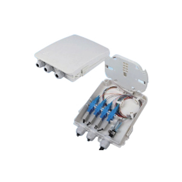
Unlike DSL or cable, which use copper wires, fiber optic Internet service relies on optical fiber to transmit data. These fiber optic cables, made of glass or plastic, use light pulses instead of electrical signals, enabling high-speed Internet with low latency and reliable. The process involves a combination of national infrastructure, local engineering, and property-level setup. In this guide, we'll break down the fiber installation process from start to finish and explain key components such as fiber cabinets, flower pods, ducting, and ONT setup. What Is Fiber Optic. Fiber optic internet represents a significant leap forward in broadband technology, offering speeds and reliability far exceeding traditional cable or DSL connections. Check availability first by contacting your internet service provider or visiting their website—fiber now passes over 76 million. The fiber is connected to an Optical Network Terminal (ONT) inside or outside your home. The ONT converts the light from th e fiber into electrical signals that run via an ethernet cable. This fundamental difference is the key to its superior speed, bandwidth, and reliability. The light signals travel at near the speed of light.
[PDF]

In this guide, we'll walk you through the entire process of preparing fiber optic cable for splicing and termination to fiber connectors. We'll explore the necessary tools, safety precautions, and step-by-step procedures for cable connectors, mechanical and fusion. At the heart of any robust fiber optic network lies a crucial process: Preparing a fiber cable for termination of a connector or splice. Two types of splices are used in fiber optic cabling one is Mechanical the other is Fusion. Whether you're installing a new network, expanding an existing one, or. Splicing fiber optic cable is an extremely important phase for making dependable, high-speed communication infrastructures. Regardless of the type of fiber network you're deploying, be it for telecom, enterprise data centers, or smart city infrastructure, fusion splicing provides the benefits of. Think of a fiber optic cable splice as the seamless stitching that keeps data flowing through the delicate threads of a network—like a master tailor joining fabric with precision. This article explains when. We terminate fiber optic cable two ways - with connectors that can mate two fibers to create a temporary joint and/or connect the fiber to a piece of network gear or with splices which create a permanent joint between the two fibers. These terminations must be of the right style, installed in a. So in essence, fiber optic splicing is a process used to join two separate fiber optic cables together.
[PDF]

The machine is a hand-held free-to-height cable quick-attachment tool with internal components such as controllers that automatically complete all steps of cable tying. It can be widely used in the high-altitude operation in the field of communication engineering and is. Power Source: Rechargeable lithium battery Bundling range: 0-60mm Binding : can binding 1600 times for one time fully charger. Voltage: 12V Battery: 7800 mAh/group, Fully charged, one battery can work more than 1600 times, about 3 kilometers or more Battery installation mode: external and embedded. Delivery time is estimated using our proprietary method which is based on the buyer's proximity to the item location, the shipping service selected, the seller's shipping history, and other factors. Delivery times may vary, especially during peak periods. Buyer pays for return. Buy Newly Designed Second Generation High Altitude Optical Fiber Cable Bundling Machine for Efficient Network Installation at Aliexpress for. Find more 1420, 153713 and 1537 products. Enjoy ✓Free Shipping Worldwide! ✓Limited Time Sale ✓Easy Return. Maximum order quantity: 1 piece Customized logo (+ from /Min.
[PDF]

Bury cables from 12-36 inches (or 30-90 cm) deep. Where plant life, sidewalks, and other utilities already disrupt earth, it's safer to bury at as little as 24 inches or 60 cm, using protective conduits to limit the likelihood of damaged cables by inexperienced maintenance or. Bury cables from 12-36 inches (or 30-90 cm) deep. However, simply hitting this depth isn't enough to guarantee your network survives. Factors like the. Requirements vary based on location, cable type, and local regulations, with depths typically ranging from 18 to 48 inches. Residential areas require depths between 24 and 36 inches for most installations. This protects cables from landscaping activities and minor excavation work. This. The question of how deep to bury fiber optic cable has no single answer, as the required depth changes significantly based on location, environment, and specific application. Industry standards and regulations, such as those often referenced in the National Electrical Code (NEC), establish a. Fiber optic cables are typically buried between 12 and 36 inches (30–90 cm), depending on installation environment, soil conditions, and load requirements. In high-load areas such as roads or backbone routes, burial depth can reach 48 inches (120 cm) or more. This guide provides a comprehensive overview of industry.
[PDF]

Tray cables (TC) are multi-conductor cables designed and rated for installation in cable trays and raceways or supported by messenger wires. To that end this Bulletin is intended to discuss the types of cables most frequently used in cable trays and the wiring methods permitted in cable trays under the National Electric Code (NEC) NFPA 70. Unlike standard electrical cables, tray cables feature enhanced insulation and jacketing to withstand mechanical stress and exposure to oil, sunlight. Low voltage power cables—rated up to 1 kV (0. 6/1 kV)—form the foundation of modern electrical distribution in residential, commercial, industrial, and data center environments. Understanding their construction, typical uses, and the standards that govern their design and installation is essential. Most low voltage cables operate at 90°C in wet or dry conditions. Manufacturers test cables to ensure they meet mechanical, electrical, and thermal performance standards. Their performance is directly related to power safety, energy efficiency and equipment life. With the acceleration of industrialization and urbanization, the.
[PDF]
The three primary types of fiber optic cable are single-mode fiber (SMF), multimode fiber (MMF), and plastic optical fiber (POF), each designed for specific applications based on distance, bandwidth, and cost considerations. Fiber optic cables transmit data as light, enabling faster and more reliable communication than traditional copper wires. Unlike copper wires, which are limited by lower data transmission speeds, shorter transmission distances, and higher susceptibility to electromagnetic interference, fiber optic cables offer unparalleled performance and can. While copper-based solutions (such as Cat5e/Cat6 for twisted pair or RG-6 for coaxial) have long served as workhorses for local and broadcast networks, fiber optic cable have seen explosive growth over the last decade. You'll learn what sets these cables apart, when to use each type, and how to avoid common installation mistakes. Whether you're. There are three main types of fiber optic cable. These are single-mode, multimode, and plastic optical fiber. Each type is good for different uses. Single-mode fiber sends data far away. The choice of fiber optic cable depends on the specific needs of the application, as well as the.
[PDF]

The optical power meter is similar to the voltohmmeter in application but measures the optical resistance (losses measured in dBm or dBM) of a cable before and after installation and provides a comparative analysis of the splices. The range of the meter is adjustable. Regularly testing fiber optic cables helps minimize network downtime, lengthens the network's longevity, reduces maintenance requirements, and helps support network reconfiguration and upgrades. These factors significantly add to the fiber optic network's long-term performance, manageability, and. Several types of tests are commonly conducted to assess and maintain the health of fiber optic networks. Continuity testing verifies that the fiber is intact and that light can pass through from one end to the other without any blockages. These test procedures assess the physical and functional qualities of fiber optic cables, connectors, and the network as a whole. Key tests include: Effective fiber testing utilizes advanced tools such as Optical. One way to test a splice is to use an Optical Power Meter. As the components like fiber, connectors, splices, LED or laser sources, detectors and receivers are being developed, testing confirms their performance specifications and helps. Regular testing of fiber optic cables is not just a preventive measure; it's an investment in the longevity and efficiency of your network. By identifying potential issues early, you can enhance.
[PDF]
Long Expansion Cycle: Optical fiber preform production has high technological barriers, and the expansion cycle can take as long as 18-24 months. Even if manufacturers start expanding immediately, the new capacity will not be available until at least 2027. This phenomenon is the result of multiple factors, including tight supply of optical fiber preforms (preforms), long expansion cycles for optical fiber production capacity, and the explosive growth of emerging applications such as AI computing power and drones. The expansion cycle of optical fibers is generally less than 6 months, and fiber optic cables can take 3 months. The expansion of production requires the purchase of equipment and the construction of factories. At the heart of this transformation lies fiber optic cable manufacturing, a precise and sophisticated process that powers our interconnected world. With the global fiber optic market reaching $6 billion and growing at 10% annually, the need for high-quality manufacturing solutions has never been. The manufacturing process of fiber optic cables involves several intricate steps that culminate in the production of high-performance data transmission solutions. This process begins with the creation of a preform, which serves as the foundation for the optical fibers within the cable. This intricate process combines cutting-edge technology, precise engineering, and.
[PDF]