This report lists the top Fusion Splicer companies based on the 2023 & 2024 market share reports. Mordor Intelligence expert advisors conducted extensive research and identified these brands to be the leaders in the Fusion Splicer industry. Fujikura Europe Ltd offers fusion splicers, which are essential for efficiently joining optical fibers. As the official support center for Fitel splicers, OFS. AFL - Fiber optic cable, transmission and substation accessories, outside plant equipment, connectors, fusion splicers, test and inspection equipment. Discover how these fusion-spliced, field-installable connectors simplify installation and improve performance. Are you looking for a professional and reliable fiber optic products manufacturer for your business? Are you still worried about how to find and select a best partner from so many fiber optic products manufacturers? Don't be afraid, Gcabling will help you. In this post, Gcabling, as a professional. Fiber splicing is the process of joining optical fibers to create continuous, low-loss optical pathways used in manufacturing, research, and high-performance fiber systems. In advanced applications, fiber splicing is not a single operation. They are headquartered in locations across the globe, including the United States, China, Brazil, and India, with founding years ranging from 1964 to 2019.
[PDF]

Unlike DSL or cable, which use copper wires, fiber optic Internet service relies on optical fiber to transmit data. These fiber optic cables, made of glass or plastic, use light pulses instead of electrical signals, enabling high-speed Internet with low latency and reliable. The process involves a combination of national infrastructure, local engineering, and property-level setup. In this guide, we'll break down the fiber installation process from start to finish and explain key components such as fiber cabinets, flower pods, ducting, and ONT setup. What Is Fiber Optic. Fiber optic internet represents a significant leap forward in broadband technology, offering speeds and reliability far exceeding traditional cable or DSL connections. Check availability first by contacting your internet service provider or visiting their website—fiber now passes over 76 million. The fiber is connected to an Optical Network Terminal (ONT) inside or outside your home. The ONT converts the light from th e fiber into electrical signals that run via an ethernet cable. This fundamental difference is the key to its superior speed, bandwidth, and reliability. The light signals travel at near the speed of light.
[PDF]

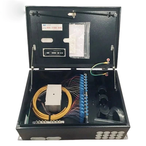
Extending the fiber through the box makes use of a cable entry gland. Fasten the cable to the clamps or ties to assure the cable is immovable. Cable must be properly minimum radius (usually ≥30mm for standard fiber). Remove the cable jacket and buffer coating material. Thus, a fiber termination box is used to terminate the optical fiber cables in the field and connect them to the pigtail by splicing. After an optical cable arrives at the user's end, it is fixed in the terminal box. Fiber adapters: These are used to connect the fiber optic cables to the fiber termination box and should comply with industry. Teleweaver emphasizes the importance of choosing the right FTB based on specific requirements. The common types include: Wall-Mounted FTBs: Ideal for residential and small-scale applications, these are compact boxes designed to be mounted on walls for easy access and space-saving cable management. To address this problem, the fiber termination box (FTB) was created to protect the fragile fiber terminals and provide a simple and clear way to manage the incoming and outgoing cables. more Order it here: https://www. This video shows you a step-by-step instruction on how to terminate 12 strands single mode fiber cables, splicing them with fiber optic pigtails.
[PDF]
In telecommunications, a base station is a fixed transceiver that is the main communication point for one or more wireless mobile client devices. It further connects the device to other. A communication base station is composed of a computer room, base station, antenna, feeder line (transmission line between transmitter and antenna), and supporting equipment. The antenna is at the top of the signal tower, and below the tower is a computer room. Along with increased capacity demands driven by the explosion of cloud and connected device growth, engineers need interconnects that enhance the design. A base transceiver station (BTS) or a baseband unit (BBU) is a piece of equipment that facilitates wireless communication between user equipment (UE) and a network. UEs are devices like mobile phones (handsets), WLL phones, computers with wireless Internet connectivity, or antennas mounted on. Fiber Optic Cables: High-speed fiber optic cables connect the BBU to the RRUs (RE part). Signal Transmission: The optical signals carry data, control, management, and synchronization information. Topology: The BBU and multiple radio heads can be connected in cascade or star configurations. The rise. The design investigates the possibilities of Free-Space Optical (FSO) communication systems and MilliMeter-Wave (MMW) technologies operating at 60. Although these technologies are highly effective and have a high throughput, they are nevertheless vulnerable to weather phenomena like rain.
[PDF]
On average, commercial projects range from $5,000 to $20,000 per mile underground and $40,000 to $60,000 per mile for aerial deployment. Individual business connections often cost between $15,000 and $30,000 for 100–200 network drops. Buying fiber optic installation services involves several cost components, with total price influenced by length, location, and access. The main cost drivers include trenching or aerial deployment, materials, labor hours, and any required permits. This guide presents typical price ranges in USD to. The initial cost of installing fiber optic cables can vary depending on the chosen installation method and specific project requirements. In preparing this second edition of the Fiber Deployment Cost report, Cartesian gathered inputs from a wide variety of firms building. Getting accurate cost estimates is crucial for winning fiber installation bids. Smart contractors know that underground vs aerial installation pricing varies wildly based on location and project conditions. This breakdown gives you real numbers to build better estimates. We'll show actual costs for. Home and business buyers typically see a wide range of costs for fiber optic projects, driven by distance, fiber type, conduit needs, and labor. The price can shift based on underground vs. aerial routes, equipment choices, and whether new permits are required. Some variables are less determinate.
[PDF]

Fiber optic terminal boxes provide functions such as input, branching and splicing of optical fiber cables. Through the connectors and splicing boxes in the terminal box, optical fibers can be quickly connected and repaired. Serving as a critical connection point, FTB facilitates the termination, splicing, or connection of fibers from various cables to other network devices such as switches, routers, or Optical Network Terminals (ONTs). It aids in splicing, splitting, storing, and managing fibers within the appropriate. The optical fiber terminal box is the terminal joint of an optical cable, one end of which is an optical cable, and the other end is a pigtail, which is equivalent to a device that splits an optical cable into a single optical fiber. A fiber pigtail is a specific hardware connection used for cable termination. It is a small enclosure that can house and protect the fiber optic cables, splices, and connectors. The optical fiber termination box and optical fiber splice box serve distinct purposes and are not interchangeable.
[PDF]

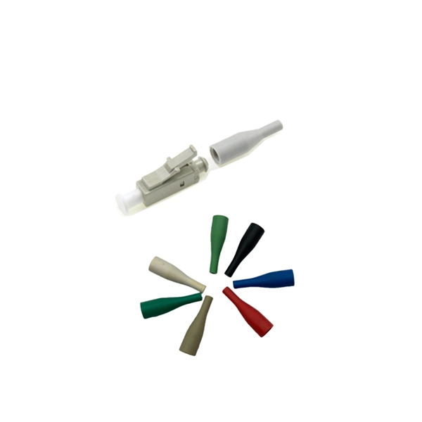
Mainly 9steps: Step 1: cut cable with cutting machines in lengths Step 2: put the connector spare parts on the cable Step 3: Strip cable jacket, coating till bare fiber, and make all parts in ready Step 4: Insert fiber into ferrule, glue dispenser and heat oven Step 5:. Mainly 9steps: Step 1: cut cable with cutting machines in lengths Step 2: put the connector spare parts on the cable Step 3: Strip cable jacket, coating till bare fiber, and make all parts in ready Step 4: Insert fiber into ferrule, glue dispenser and heat oven Step 5:. Learn how to make a fiber optic patch cord step by step, from preparation to testing, for reliable high-performance connections. Most guides on making fiber optic patch cord 1 s feel incomplete. They often focus on the final assembly steps, leaving the foundational stages a mystery. From cable cutting to connector assembly and testing, you will gain valuable insights into the production of. Fiber optic patch cords and Pigtails are very important passive fiber optic components in fiber optic networks. Use the fiber optic cleaver to cut the. This document describes the installation and use of the mode-conditioning patch cords listed in Table 1. A mode-conditioning patch cord is shown in Figure 1 IEEE 802. 3z-compliant optical fiber assembly consisting of a single-mode fiber permanently coupled off-center to a 62. 5-micron multimode.
[PDF]
There are hybrid optical and electrical cables that are used in wireless outdoor Fiber To The Antenna (FTTA) applications. In these cables, the optical fibers carry information, and the electrical conductors are used to transmit power. These cables can be placed in several environments to serve antennas mounted on poles, towers, and other structures. According to Telcordia GR-3173, Gener. OverviewA fiber-optic cable, also known as an optical-fiber cable, is an assembly similar to an but containing one or more that are used to carry light. The optical fiber elements are typically individually. Optical fiber consists of a and a layer, selected for due to the difference in the between the two. In practical fibers, the cladding is usually coated wit. In September 2012, NTT Japan demonstrated a single fiber cable that was able to transfer 1 per second (10 bits/s) over a distance of 50 kilometers. Although larger cables are available, the highest stra.
[PDF]

Bury cables from 12-36 inches (or 30-90 cm) deep. Where plant life, sidewalks, and other utilities already disrupt earth, it's safer to bury at as little as 24 inches or 60 cm, using protective conduits to limit the likelihood of damaged cables by inexperienced maintenance or. Bury cables from 12-36 inches (or 30-90 cm) deep. However, simply hitting this depth isn't enough to guarantee your network survives. Factors like the. Requirements vary based on location, cable type, and local regulations, with depths typically ranging from 18 to 48 inches. Residential areas require depths between 24 and 36 inches for most installations. This protects cables from landscaping activities and minor excavation work. This. The question of how deep to bury fiber optic cable has no single answer, as the required depth changes significantly based on location, environment, and specific application. Industry standards and regulations, such as those often referenced in the National Electrical Code (NEC), establish a. Fiber optic cables are typically buried between 12 and 36 inches (30–90 cm), depending on installation environment, soil conditions, and load requirements. In high-load areas such as roads or backbone routes, burial depth can reach 48 inches (120 cm) or more. This guide provides a comprehensive overview of industry.
[PDF]

A cable management rack is designed to route, protect, and organize copper and fiber cables inside network cabinets. Beyond keeping cables tidy, a well-structured cable manager reduces cable stress, improves heat dissipation, and ensures bend-radius compliance for data transmission. This article provides a clear technical view of cable management racks, their structures, and how to select the right solution for modern networks. Cable management in server racks simply refers to organizing, routing, and securing power and data cables so they stay neat, accessible, and. Simply put, a cable rack is a structured set of shelves designed to organize, protect, and manage cables in various settings. These racks range from simple, affordable options to complex, high-capacity models that accommodate a vast number of cables. The benefits of using cable racks are numerous. Horizontal cable management is a cornerstone of efficient IT infrastructure, ensuring that server racks and enclosures remain organized, accessible, and functional., Ethernet, fiber optic, coaxial). At its core, it aims to: Minimize cable tangling, kinking, and wear. Simplify troubleshooting and maintenance. As businesses increasingly rely on robust network infrastructure, proper cable organization becomes critical for.
[PDF]
Unlike traditional metal-style reels, MARS is a lightweight, modular system constructed of an impact modified polymer that is easily transported. It is ideal for applications where cable needs to be deployed and reeled in quickly and stored efficiently. OCC's Modular Advanced Reel System (MARS ®), the industry's first lightweight cable deployment reel system, is designed specifically for the demanding needs of harsh-environment fiber optic installations. The dual take-ups are designed to work independently from line controls, therefore providing an easy adaptation and a fast plug & play installation to any line.
[PDF]

The optical power meter is similar to the voltohmmeter in application but measures the optical resistance (losses measured in dBm or dBM) of a cable before and after installation and provides a comparative analysis of the splices. The range of the meter is adjustable. Regularly testing fiber optic cables helps minimize network downtime, lengthens the network's longevity, reduces maintenance requirements, and helps support network reconfiguration and upgrades. These factors significantly add to the fiber optic network's long-term performance, manageability, and. Several types of tests are commonly conducted to assess and maintain the health of fiber optic networks. Continuity testing verifies that the fiber is intact and that light can pass through from one end to the other without any blockages. These test procedures assess the physical and functional qualities of fiber optic cables, connectors, and the network as a whole. Key tests include: Effective fiber testing utilizes advanced tools such as Optical. One way to test a splice is to use an Optical Power Meter. As the components like fiber, connectors, splices, LED or laser sources, detectors and receivers are being developed, testing confirms their performance specifications and helps. Regular testing of fiber optic cables is not just a preventive measure; it's an investment in the longevity and efficiency of your network. By identifying potential issues early, you can enhance.
[PDF]

Our extensive offering of fiber optic cables, connectors, cassettes, enclosures, patch cords, cable assemblies, cable distribution products and accessories deliver high performance, reliability, and scalability. Precision Fiber Products, Inc. offers a wide range of fiber optic products. We specialize in fiber optic interconnect components, including fiber optic cables, connectors, cable splicing, ferrules, and more. Ready to get started? Get a quote now! In just a few steps, you can receive a quote. ESTABLISHED IN 1976: Selected three times as an "INC 500" company. Designated as one of the "Hottest VAR/Distributors". Delivering high performance, reliability, and scalability, the Base-16 Fiber Cabling. Belden's extensive line of indoor and outdoor cable products is offered in tight buffer and loose tube designs. Armored, burial, and ruggedized designs are suited to a host of industrial environments. For each product design, items for OM1, OM3, OM4, OM5, and OS2 (Singlemode) items have been. Cables. com (Datacomm Cables, Inc. ), is headquartered in Long Island, New York (Deer Park, NY). Since 2001, Datacomm Cables has been a single source offiber optic cables,networking cables,power cords,crypto cables, datacenter cables,Cat5 cables,Cat6 cable,Cat6A cable,shielded cables,outdoor cables.
[PDF]