This guide describes the general requirements, functional and technical performance requirements, test requirements, labeling and packaging requirements, transportation and storage requirements, supply integrity requirements, and quality assurance requirements for hybrid high-voltage. This guide describes the general requirements, functional and technical performance requirements, test requirements, labeling and packaging requirements, transportation and storage requirements, supply integrity requirements, and quality assurance requirements for hybrid high-voltage. Guide for Technical Requirements for Hybrid High-Voltage Direct Current Transmission Protection and Control Equipment This guide describes the general requirements, functional and technical performance requirements, test requirements, labeling and packaging requirements, transportation and storage. purpose of this white paper is to aid WECC members (Specifier) in specifying and applying relay systems that will provide adequate protection of extra-high voltage (EHV) on 345-kV or higher transmission lines and comply with the NERC Reliability Standards. The recommendations in this white paper.
[PDF]
of relay protection coordination for a PV power plant connected to the distribution network is presented. In recent years, installation of PV power plants in the distribution network has increased significantly. I.
[PDF]
The procedures of testing switchgear, instrument transformers and relays are explained in detail. The close and trip, indication and alarm circuits for variety of circuit breakers indicating ferrule numbers are al.
[PDF]

In this video, I'll show you how to build a simple and effective short circuit protection circuit using a relay. This DIY project is perfect for anyone looking to protect their electronics from accidental shorts. Last Updated on February 15, 2026 by Swagatam 117 Comments In this post I will try to explain the making of a simple 220 V, 120 V AC mains short circuit breaker using an SCR and a triac combination, (researched and designed by me). The circuit is an electronic version of the normal main circuit. One possible solution to the problem of overcurrent is to use a variable bench power supply with a current limit function. These power supplies allow You to set a current limit, preventing a high current flow when a mistake occurs. This circuit will. Why Publish? How to Make Short Circuit Protection Circuit: Hii friend, Today I am going to make a circuit for Short Circuit protection. This circuit we will make using 12V Relay. How this circuit will Work - when short circuit will occur on the load side then the circuit will be automatically cut o. In this tutorial, we will see how to make a short circuit protection using Relay. Many times accidentally terminals of batteries and other power supplies get short-circuited. Due to this, they get hot and start degrading. In the case of lithium-ion or lithium-polymer batteries, they may catch fire.
[PDF]

Energy Internet integrates small-scale renewable energy systems, electric loads, storage devices, and electric vehicles for effective transaction of power backed by emerging technologies such as Internet of Things, vehicle-to-grid, and blockchain. Energy Internet, a futuristic evolution of electricity system, is conceptualized as an energy sharing network. Some studies have even offered protocols and designs, but there hasn't been any comprehensive look at the technology involved thus far. If we want to work towards a standardised version of. This textbook is the first of its kind to comprehensively describe the energy Internet, a vast network that efficiently supplies electricity to anyone anywhere and is an internet based wide area network for information and energy fusion. The chapters are organized into five parts: Architecture and. Taking the Internet as a paradigm, a practicable design of the Energy Internet is presented based on the principle of standardization. A combination of stylized data and energy delivery, referred to as a Block of Energy Exchange (BEE), is designed as the media to be communicated, which is parsed by.
[PDF]
The communication system of fiber optics is well understood by studying the parts and sections of it. The major elements of an optical fiber communication system are shown in the following figure. The ba.
[PDF]
Modern fiber-optic communication systems generally include optical transmitters that convert electrical signals into optical signals, to carry the signal, optical amplifiers, and optical receivers to convert the signal back into an electrical signal. The information transmitted is typically generated by computers or.
[PDF]

This paper describes a reliable substation protection system that involves busbar protection, station-wide breaker failure protection, and advanced zone selection. IV EXECUTIVE. GE Multilin provides protective relays that support all busbar protection techniques, including overcurrent, high-impedance differential, and percentage (low-impedance) differential. GE Multilin. Modern numerical relays use innovative algorithms to fulfill busbar protection requirements of fast operating times for all busbar faults, security for external faults with heavy CT saturation, and minimum delay for evolving faults. Busbar protection is critical for the safe and reliable operation of a power system. Related Article: Busbar Protection Like any other faults. As a professional transformer and switchgear manufacturer, Hangbian Power Technology Co. provides customers with a complete set of power equipment solutions, including high- Voltage Switchgear, low-voltage distribution cabinets, box type substations, etc. The core value of the busbar. A busbar protection is a protection to protect busbars at short-circuits and earth-faults. In the “childhood” of electricity no separate protection was used for the busbars. With increasing short-circuit power in the network.
[PDF]
Optical splitters play a crucial role in Fiber to the Home (FTTH) Passive Optical Network (PON) systems, efficiently distributing a single optical signal to multiple destinations. The split ratio and insertion loss are two key parameters defining their performance. Understanding Fiber Optic Splitters: Principles, Parameters, Types, Applications, and Future Trends 1. Introduction Fiber optic splitters are integral components in the world of optical networks. A deeper understanding of these. 📄 What is an Optical Splitter? An Optical Splitter, also known as a beam splitter, is a passive optical device that divides a single input optical signal into two or more output signals. Conversely, it can also combine multiple signals into one. Its primary role is in Passive Optical Networks. Bandwidth is shared amongst customers in a PON, and the bandwidth received by a customer is not related to the power received at the optical network terminal (ONT) as long as the power is high enough so the ONT can operate. Their ability to efficiently manage optical signals makes them indispensable in various. The performance of optical beam splitters can significantly influence the overall performance of laser-based instrumentation and measurement systems. This paper examines two of the most critical performance factors: optical efficiency and wavefront distortion. Efficiency is a function of both the.
[PDF]

In optical transmission systems, there are three key elements: the transmitter (laser and modulator), the photodetector, and the optical transmission medium (the fiber). Typically, the detector is characterized by a level of sensitivity to impinging optical power. However, as many optical channels travel in a fiber strand, many interesting phenomena take place. Light interacts with mat- of high quality, the received signal may have been contaminated. Therefore, the system and network. This is the second book on performance of optical channels, systems, and. Optical communication systems transfer information over distances using light instead of electrical current. These systems convert electrical signals, which carry data, into pulses of light and then back into electrical signals at the destination. The optical transmitter and the optical receiver. As an essential component of optical fiber communication, optical modules are optoelectronic devices that facilitate the conversion between optical and electrical signals during the transmission process. Most of the systems utilize a transceiver which. tion assisted by digital signal processing (DSP). The objective of this tutorial chapter is to briefly review the operating principles of state-of-the-art ong-haul coherent optical communications systems. Photonic systems are usually analyzed in terms of individual photons, although wave methods still.
[PDF]

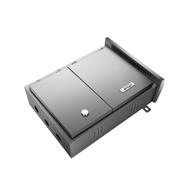
This guide is intended to present the fundamentals of power system design for commercial and industrial power systems. A distribution board, also known as a panel board or breaker panel, is an enclosure that houses electrical components such as circuit breakers, fuses, and busbars. Its primary function is to distribute electrical power from a main supply to various circuits while providing protection against. These Distribution Boxes enable decentralized installation of the electronics close to the load. The range of applications extends from pure energy distribution in buildings to building automation and through to industrial plants. SMART DISTRIBUTION BOXES FOR FLEXIBLE BUILDINGS. It is a vital part and central hub of any electrical system. Whether it's a home, office, or factory. Electrical distribution system design is a critical aspect of industrial facility engineering that determines how electrical power is delivered from the utility service to end-use equipment. A well-designed distribution system provides reliable power, adequate capacity, proper protection, and. In industrial power distribution systems, cable distribution boxes (also known as power distributor boxes, distribution electrical boxes, or electrical power distribution boxes) are the core hub of power transmission, branching, and protection. Its layout directly affects the efficiency of the.
[PDF]
WDM systems are divided into three different wavelength patterns: normal (WDM), coarse (CWDM) and dense (DWDM). Normal WDM (sometimes called BWDM) uses the two normal wavelengths 1310 and 1550 nm on one fiber. Coarse WDM provides up to 16 channels across multiple transmission windows of silica fibers. OverviewIn, wavelength-division multiplexing (WDM) is a technology which a number of signals onto a single by using different (i.e., colors) of. A WDM system uses a at the to join the several signals together and a at the to split them apart. With the right type of fiber, it is possible to have a device that does both s.
[PDF]

These numerical codes, ranging from 1 to 99, uniquely identify the functions of protective relays, associated devices, and control equipment in electrical power systems. In electric power systems and industrial automation, ANSI Device Numbers can be used to identify equipment and devices in a system such as relays, circuit breakers, or instruments. The device numbers are enumerated in ANSI / IEEE Standard C37. 2 Standard for Electrical Power System Device Function. According to the ANSI/IEEE standards, device function numbers are crucial identifiers in power system protection and control engineering. ANSI IEEE Standard Device Numbers are below: (the more commonly used ones are in bold) 86T is a Lockout Relay for a. The widely used United Sates standard ANSI/IEEE C37. Even in those parts of the world where IEC standards are predominate, the use of ANSI numbering. For power grid systems, ANSI and IEEE functional number codes dictate the use and restrictions of both the devices themselves, as well as the functions of those devices within the scope of a circuit. These devices include switches, disconnects, circuit breakers, generators, and motors. Instead of verbal descriptions, we use numbers to describe the functions of a relay. Why use numbers instead of words? Efficiency.
[PDF]