
Pellicle beam splitters are made from an extremely thin membrane, often nitrocellulose, stretched over a frame. Their minimal thickness minimizes absorption and eliminates ghost images, which are secondary reflections that can degrade optical performance. Beamsplitters are fundamental components in optical engineering, serving to precisely divide a single input beam of light into two distinct output beams. This division allows for the simultaneous analysis or utilization of the light's properties along two separate paths. Their precision and versatility make them indispensable in a variety of scientific, industrial, and technological applications. These versatile tools can split both laser and regular light, depending on the application in question. Additionally, beamsplitters can be used in reverse to combine two different beams into a single one. It is a crucial part of many optical experimental and measurement systems, such as interferometers, also finding widespread application in fibre optic telecommunications. However, how they work exactly often remains overlooked. This article covers all you need to know about.
[PDF]

At its core, an overcurrent relay operates on a very simple concept: detect excessive current, then trip fast and isolate the fault. When current surpasses the relay's pickup setting, an internal mechanism triggers the circuit breaker. IEEE/IAS/I&CPSD Protection & Coordination WG Chair Jacobs Canada, Calgary, AB rasheek. com IEEE Southern Alberta Section PES/IAS Joint Chapter Technical Seminar - November 2016 Protective Relays - Technical Seminar Nov 2016 - Copyright: IEEE 2 Abstract: Protective relays and devices. Relay protection against high current was the earliest relay protection mechanism to develop. From this basic method, the graded overcurrent relay protection system, a discriminative short circuit protection, has been formulated. Types of over current relay. It is really current monitoring relay. Overcurrent Relay Definition: An overcurrent relay is a protective device that operates solely based on current without the need for a voltage coil. These relays are known for their speedy operation during a fault and are hence used widely in high-voltage applications. Let's know in. The Art and Science of Protective Relaying, by C. Mason, John Wiley and Sons, 1956. Evaluation of Distribution System Relaying Methods, by A. McConnell, Presented at the Pennsylvania Elec-tric Association, May 16-17, 1957.
[PDF]

Companies like Tesla, CATL, and Fluence are deploying battery farms that can store megawatts of solar power and release it on demand. Meanwhile, “smart grids” enabled by AI and real-time data are helping to balance supply and demand dynamically. Energy Internet technology promotes the deep integration of energy and communication infrastructure and creates an open and shared Internet ecosystem. The energy Internet theory has been not only applied to the industrial field but also developed to be used in the agricultural field (Fu and Yang. From the first fires that lit our ancient caves to the towering smokestacks of the Industrial Revolution, each leap forward in power generation has redefined how we live, work, and relate to the planet. But the fossil fuel era—so dominant, so defining—is reaching its inevitable twilight. The signs. ITM University Gwalior, India. coordinating and controlling the many parts of a system, whether they are locally located or geographically dispersed. The study wraps up by outlining the most pressing problems that will need to be solved in order to implement an.
[PDF]
Choose the right box based on environment (indoor/outdoor), load capacity, and durability. Check for proper IP/NEMA ratings and material quality. Ensure safe placement: install in dry, accessible areas with good ventilation and at appropriate height (typically ~1. Practice good wiring: secure. An electrical distribution box, also known as a power distribution box, panelboard, or consumer unit, is the core of an electrical system. It has three categories: residential, commercial and industrial electrical distribution boxes, all of which play important roles in their respective electrical. When you install a distribution box, you need a variety of tools to get the job done safely and efficiently. To install distribution box systems, you'll use hand tools such as screwdrivers and pliers. Wire strippers are essential when you install distribution box wiring. A measuring tape and. This guide offers an in-depth exploration of installing electrical distribution boards, highlighting essential steps, safety measures, and the integration of business intelligence tools to optimize your work. Just like travelers need clear pathways and safety protocols, your electrical circuits need proper management to prevent chaos. The National Electrical Code (NEC) requirements might seem like bureaucratic.
[PDF]
The various protective functions available on a given relay are denoted by standard. For example, a relay including function 51 would be a timed overcurrent protective relay. An overcurrent relay is a type of protective relay which operates when the load current exceeds a pickup value. It is of two types: instantaneous over current (IOC) relay and definite time overcurrent (DTOC) relay.
[PDF]

A relay protection tester is a core device used to verify the performance of relay protection devices. Its working principle can be summarized as “signal excitation – behavior detection. ”. It is divided into two parts: the main loop and the auxiliary loop. ” The tester has a built-in high-precision programmable power supply, capable of simulating various operating. When the transformer wiring type is Y/Y (Y0), the test wiring is very simple: when testing phase A, the tester IA is connected to the phase A of the high voltage side, and the tester IB is connected to the phase a of the low voltage side. After the neutral line of the high and low voltage sides is. Relay protection aids in detecting and preventing faults in electrical systems such as overcurrents or short circuits. As a core part of electric system reliability and safety, protective relays aid in preserving equipment and maintaining stability by isolating affected zones automatically via. THEY SHOULD BE GIVEN FIRST LINE MAINTENANCE ATTENTION. COMPREHENSIVE INSPECTION, MAINTENANCE AND TESTING PROGRAM. ” relay may only need to operate for 0. 15 seconds in its 30+ year life. But failure to operate as intended can result in extensive damage, extended power outages, and loss of life. NETA. Megger's smart relay testing solutions and expert support help you validate protection performance, improve system reliability, and ensure continuity of power across your network.
[PDF]

A phase-sequence relay monitors phase rotation in three-phase systems, protecting equipment from damage due to incorrect or reversed phase order. It guards a 3-phase device against any potential damage due to sequence change. They are deployed anywhere with a phase-sequence change that can damage the device or circuit. They work like a conventional electric relay. The order of these voltages is typically designated as ABC, where A, B, and C represent the phases. The correct phase sequence is vital for proper functioning and protection of various. Engineers use a Phase Failure Relay, which is additionally known as a Voltage Monitoring Relay (or) a Phase Sequence Relay to avoid costly breakdowns. This small but powerful equipment continuously monitors the state of the three-phase supply & guarantees that motors work only according to safe. A phase sequence relay is a tool that controls the correct sequence of phases in three-phase electrical systems. It is basically a special type of protective device that is used to monitor and control the sequence or order in which the phases of a three-phase power supply are connected. The primary function of a Phase.
[PDF]

Optical Pulse Position Modulation (PPM) is a digital modulation technique where information is encoded in the temporal position of an optical pulse within a predefined time frame (or slot). This is repeated every T seconds, such that the transmitted bit rate is bits per second. It is primarily useful for. Definition: A modulation technique that allows variation in the position of the pulses according to the amplitude of the sampled modulating signal is known as Pulse Position Modulation (PPM). It is another type of PTM, where the amplitude and width of the pulses are kept constant and only the. As a widely used modulation technique in the field of communication, PPM modulation techniques have the advantages of high interference immunity, simple coding and high-power utilization, and are often applied in practical scenarios. PPM modulation techniques can be divided into three categories. In this type of modulation, continuous signals are sampled at normal intervals, so this modulation technique is used to transmit analog information.
[PDF]

Optical attenuators use several principles in order to accomplish the desired power reduction. The types of attenuators generally used are fixed, stepwise variable, and. An optical attenuator is a passive device that is used to reduce the power level of an optical signal. The attenuator circuit will allow a known source of power to be reduced by a predetermined factor, which is usually expressed as decibels. Key requirements include minimal effect on the beam profile, low wavelength and polarization dependence, and sufficient power handling capability. The basic types of optical attenuators are fixed, step-wise variable, and continuously variable. Since too much light may saturate the fiber optic receiver, optical attenuators are often deployed in the system to reduce the light power and achieve the best fiber. An attenuator is a device designed to reduce the intensity of electrical and electromagnetic oscillations smoothly, stepwise, or at a fixed rate. It primarily ensures the power or amplitude of a signal is lowered without significantly distorting its waveform. Attenuators are extensively used across.
[PDF]

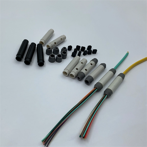
Fiber optic patch cable are used to transmit optical signals between two devices or subsystems. They work by using the principle of total internal reflection, which occurs when light travels through a material with different refractive indices. They act as the critical link for interconnecting devices like optical switches, servers, and distribution frames. Understanding the various technical. A fiber optic patch cable is a short piece of fiber with connectors on both sides. It connects one device to another, often within the same rack or across neighboring network equipment. These cables carry data in pulses of light. There are mainly two types of fiber optic patch cables: single-mode. As networks move to higher speeds and higher density, choosing the right fiber optic patch cords becomes critical to the reliability of your system. It is designed for flexible, short-distance connections within networks. They are also called fiber jumpers. It consists of two fiber connectors on each end and a fiber.
[PDF]

By dividing a single optical signal from a central Optical Line Terminal (OLT) into multiple outputs for Optical Network Terminals (ONTs) at users' homes, splitters eliminate the need for dedicated fibers to each residence—slashing infrastructure costs while scaling network reach. High-speed broadband, cloud computing, and 5G communication all rely on one critical passive component: the PLC splitter. As a core device in FTTH and PON networks, a PLC splitter is not just about “splitting light” — it's about delivering stable, low-loss, and uniform optical power distribution at. In the backbone of modern Fiber-to-the-Home (FTTH) networks, optical splitters serve as the unsung heroes that enable cost-efficient connectivity for millions of subscribers. FTTH relies on Passive Optical Network architecture, which enables one fiber leaving the central office. 📄 What is an Optical Splitter? An Optical Splitter, also known as a beam splitter, is a passive optical device that divides a single input optical signal into two or more output signals. Conversely, it can also combine multiple signals into one. Think of it as a prism for modern-day fiber optic communications – directing the light in multiple directions, but without.
[PDF]
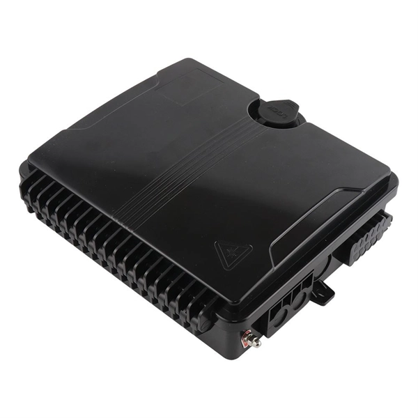
A fiber terminal box, also known as a fiber distribution box, is a device used in fiber-optic communication networks to terminate, splice, and distribute optical fibers. It is a small enclosure that can house and protect the fiber optic cables, splices, and connectors. Distribution boxes, terminal boxes, and closures are often compared because all three appear as fiber aggregation or transition points within a physical network. In diagrams and BOMs, they are frequently grouped under “fiber boxes,” leading to the assumption that they differ only in form factor or. A terminal block box, also known as a junction box or distribution box, is a closed or semi-closed enclosure that contains terminal blocks (usually in the form of screw-type, spring-type or peel-free type). Its core function is to provide a centralized connection, distribution, transfer and. A Fiber Access Terminal (FAT), also known as a Fiber Access Terminal Box (ATB) or Fiber Distribution Terminal (FDT), is a key component found in optimized fiber optic access networks for FTTH implementations. The fiber termination box.
[PDF]
