WDM, CWDM and DWDM are based on the same concept of using multiple wavelengths of light on a single fiber but differ in the spacing of the wavelengths, number of channels, and the ability to amplify the multiplexed signals in the optical space.OverviewIn, wavelength-division multiplexing (WDM) is a technology which a number of signals onto a single by using different (i.e., colors) of. A WDM system uses a at the to join the several signals together and a at the to split them apart. With the right type of fiber, it is possible to have a device that does both s. Originally, the term coarse wavelength-division multiplexing (CWDM) was fairly generic and described a number of different channel configurations. In general, the choice of channel spacings and frequency in these co.
[PDF]
BARCELONA, Spain, March 6, 2025 /PRNewswire/ — At the Mobile World Congress 2025 (MWC 2025), Huawei launched the StarryLink optical modules, designed to enhance network experiences with “3S” quality (Spanning, Stable, Secure). This announcement occurred during the data center session titled. The global optical transport market returned to growth mode in 2025, climbing 10% year over year to reach $16 billion, according to new data from Dell'Oro Group. The market, projected to reach $14. 7 billion in 2025, is forecast to.
[PDF]
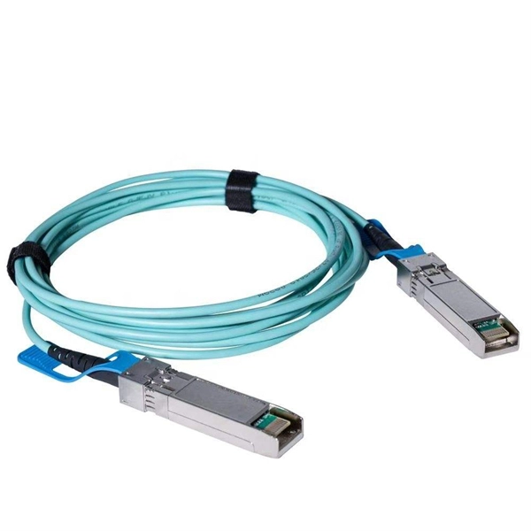
The transceiver is available as a mini-GBIC form factor, making it ideal for environments that require many fiber connections by taking up less space in your cabinet and/or computer room. Compatibility in your network is everything, and the Intellinet SFP Transceiver Module delivers. Use it with any Intellinet SFP equipped network switch or any other MSA-compliant, SFP-enabled switch. And since the Intellinet SFP transceiver module is set to broadcast the vendor on GLC-LH-SM, compatibility to your Cisco gear is provided. No need to power down your LAN switch in order to install or remove the transceiver. This makes it very convenient and easy for you to make adjustments to your network that allow your business to keep pace with the changing demands of the market.
[PDF]
This high-quality H3C Networks SFP-XG-SX-MM850-A Compatible 10GBASE-SR SFP+ 850nm 300m DOM Transceiver. A cost-effective solution that provides high bandwidth and transmission rates over short distances. Each transceiver is 100% optically inspected and tested for compatability before. Optical modules transmit signals over optical fibers. H3C devices support optical module models of different specifications. The. This H3C SFP-XG-SX-MM850-D transceiver is high performance and cost-effective SFP+ supporting data-rate of 10. 3125Gbps (10GBASE-SR) or 9. This transceiver is compliant with SFF-8431, SFF-8432 and IEEE 802. Digital diagnostics monitoring is available via a 2-wire serial interface, as specified in SFF-8472. Usually issued within 24 hours. See exceptions May apply, not eligible for free return. See details At any of our 50,000 US locations. See more product details Help others learn more about this product by uploading a video! 0. 76 ounces UBJFMAC B0GQMGC6MR UBJFMAC February. New original H3C 10G multimode optical module SFP-XG-SX-MM850-E 850nm 10G LC interface The H3C 10GBASE-SR SFP+ Optical Transceiver, MMF 850nm, 300m, Industrial Temp is guaranteed 100% Compatible and Functional in its intended equipments. Every SFP-XG-SX-MM850-E is environmentally tested in its.
[PDF]

The receiver of an optical module has an overload point. Therefore, an optical attenuator is required to reduce the optical power. By introducing a precise and constant amount of optical loss, it ensures that the incoming signal remains within the optimal operating range of the receiver. A. Average optical power refers to the optical power outputted by the optical module's transmitter under normal working conditions, which can be understood as the intensity of light. The transmitted optical power is related to the proportion of "1"s in the transmitted data signal; the more "1"s, the. The receiver of an optical module has an overload point. If the optical power received by the receiver is excessively high, the optical module will be burnt. In addition, during signal transmission in a WDM system, the. 📦 For purchasing, use the RP Photonics Buyer's Guide for optical attenuators. It provides an expert-curated supplier directory, buyer-focused technical background information, and structured selection criteria to support professional procurement decisions. Optical attenuators are devices that. An optical attenuator, or fiber optic attenuator, is a device used to reduce the power level of an optical signal, either in free space or in an optical fiber. Optical internetworks are data networks composed of routers and data.
[PDF]
In today's data-driven world, high-speed optical modules (e., 100G/400G/800G) are the backbone of modern networks, enabling ultra-low latency and massive bandwidth for data centers, telecom, and enterprise applications. However, their performance hinges on proper deployment. nd Latency variation are very important in applications requiring accurate timing (e (PAM-4 or Coherent), require complex digital signal processors (DSPs) in optic itional EEPROM data content for propagation del ss C. 2” pluggable : 2% of the cTE budget ITU-T G. 2 allocated for Class C A. 20”. This article helps trading engineers and network architects select an ultra low latency SFP that fits 10G/1G optics needs while minimizing added propagation and serialization delay. A solution for accurately measuring the Latency of PAM4 optical modules is required. Potential source of time error in complex digital parts of pluggables. Higher bit rates (50 Gb/s and higher) and. Transceiver latency is a key spec in enterprise fiber optic networks especially in financial institutions. It is the one of the few variables that can be optimized since fiber path delay is fixed. However, their performance hinges on proper deployment and maintenance.
[PDF]

Nigeria Sfp Optical Module Suppliers Directory provides list of Nigeria Sfp Optical Module Suppliers & Exporters who wanted to export sfp optical module from Nigeria. Don't know your target market? Wanted to market your Sfp . The Cisco SFP 10G SR module is meant to provide data transfer at 10Gbps speed with short-range. Qsfp-100g-sr4-s 100g sfp module s-class qsfp-100g-sr4-s 100gbase sr4 qsfp transceiver, mpo, 100m. Small Form-factor Pluggable (SFP) is a compact, hot-pluggable network interface module format used. The best choice is Cisco SFP Transceivers are the best in offering high performance and flexibility in the enterprise and data center networking. The hot-swap modules offer speeds of 1G, 10G, 25G, 40G, and 100G and will smoothly scale to various networking requirements. They come in SFP+, SFP. Fiber optic transceivers are widely used in telecommunication, CATV, FTTx, and various kinds of other data communications. Their commitment to high-quality service and tailored recommendations can support organizations looking to enhance their digital operations. Do You Really Know Where Your Transceivers Come From? Factory-direct optical transceivers and high-speed cables, from legacy links to 1. 6T, built to deploy faster, scale cleaner, and stay compatible as your network evolves. At scale, the biggest problems come from what you don't control, not what.
[PDF]
An optical module is a typically hot-pluggable optical transceiver used in high-bandwidth data communications applications. Optical modules typically have an electrical interface on the side that connects to the inside of the system and an optical interface on the side that connects to the outside world through a fiber optic cable. The form factor and electrical interface are often specified by an int. Electrical Interface TypesThere have been multiple variants of the electrical interface of optical modules that have been used over the years. The earliest forms of optical modules had an analog electrical interface. In the transmit dir. Many different forms of optical modulation and multiplexing have been employed in optical modules. The most common modulation technique historically has been or NRZ.
[PDF]
A photonic integrated circuit (PIC) or integrated optical circuit is a microchip containing two or more photonic components that form a functioning circuit. This technology detects, generates, transports, and processes light. Photonic integrated circuits use photons (or particles of light) as. architecture and performance of several generations of InP-based PICs. Increased complexity in chip functionality has resulted in a need for increased fabricati n complexity from III-V epitaxy, through wafer fab, die fab, and test. Through continuous learning and improvement, Infinera has. Photonic integrated circuits (PICs) use light (photons) to transmit information, whereas traditional integrated circuits use electricity (electrons), enabling faster signal propagation. Whereas an electronic integrated circuit.
[PDF]
The SFP-1040-WB is a BiDirectional single fiber strand 10G SFP+ optical module using Tx:1330nm and Rx:1270nm wavelengths. The transceiver supports all 10G rated speeds for Ethernet, SONET, SDH or Fibre Channel networks. SFP-1040-WB must be paired with the SFP-1040-WA model to have an operational. The SFP-1040-Wx series single mode transceiver is small form factor pluggable module for duplex optical data communications such as 10GBASE-ER/EW defined by IEEE 802. It has the SFP+ 20-pin connector to allow hot plug capability. All modules satisfy class I laser safety requirements. Digital diagnostics functions are available via a 2-wire serial. The SFP-1040-Dxx is a DWDM 10G SFP+ optical module. It is available for all 45 DWDM 100GHz ITU grid wavelength channels. The transmitter section uses a 1550nm EML, which is class 1 laser compli Rate Select 0, optionally controls SFP+ module recei e Select 1, optionally controls SFP+ module.
[PDF]

The transmitter optical power ranges from +3 to +7 dBm, while receiver sensitivity reaches -30 dBm, supporting distances up to 20 kilometers over standard single-mode fiber infrastructure. Note 1: Measured with 1310nm, 1. 244Gbps PRBS223- 1 burst-mode optical input, ER= 10dB, BER= 1x10⁻¹⁰; Single burst packet length is 40us and packet interval is 40us. Note 2: Input optical power level difference of adjacent burst packets. Note 3: Receiver optical power ranged from -8dBm to -28dBm. designed for FTTH GPON applications. Packaged in a Small Form- infrastructure in edge, enterprise, or distributed environments. robust fiber-to-the-home (FTTH) or small-scale fiber deployments. temperature, voltage, bias current, and optical power. On the uplink side, it operates. Max. Supporting 20km over single-mode fiber with 1490/1310nm wavelengths, this module delivers 33 dB link budget for 1:64 or 1:128 split ratios at 2. 488 Gbps downstream and 1. SC/PC connector for OLT PON port integration. Complete technical specifications and product details Our. Cisco ME Series products support any fiber-based (FTTx) access scenarios, including Fiber To The Home (FTTH), Fiber To The Building (FTTB), Fiber To The Curb (FTTC), Fiber To The cell (FTTc), and Fiber To The business (FTTb). Figure 1 illustrates the Cisco GPON solution. The Cisco GPON. The following tables list the performance specifications for the various functional blocks of the integrated optical transceiver module.
[PDF]

There are a total of 113 Optical Products Manufacturers in Peru as of August 15, 2024. (Google Earth) file formats. Identify and compare relevant B2B manufacturers, suppliers and retailers Max. The company, Opeluce Eye Clinic, specializes in comprehensive care for ophthalmological issues, utilizing advanced diagnostic and treatment technologies for ocular diseases. Their expert ophthalmologists and. To help you choose the best partner, this article will analyze and introduce 10 companies in the optical transceiver industry chain for you. Armotec is a prominent Peruvian company specializing in high-tech measuring instruments, including optical sensors like photoelectric sensors. They offer a variety of products and emphasize their ability to meet the needs. After gathering significant public information from various online sources and conducting relevant analysis and comparisons, we have compiled a list of the leading optical transceiver manufacturers based on market share. 63% increase from 2023. We are dedicated to helping you build, connect, protect and optimize your network. Topstar focuses on R&D and has our Top-trans” brand SFP/SFP+/XFP+QSFP/CFP/QSFP28 series of modules, we offer 24*7 hours online service.
[PDF]
An OLT consists of three major parts: 1. Service port interface function - Provides translation between service interfaces and the TC frame interface of the PON section. 2. Cross-connect function - Provides a c.
[PDF]