This section applies to grounding of transmission and distribution lines and equipment for the purpose of protecting employees. Note to paragraph (a): This section covers. Correct grounding of services depends upon understanding the definition and role of the grounded conductor. The neutral conductor is typically the grounded conductor connected to the system's neutral point, carrying current under normal operation. Grounding electrode conductors must be connected at. Learn the grounding and bonding rules when powering two or more buildings or structures in the same area with a single service. To catch up on Lorenzo Mari's series on National Electrical Code 2023 Basics: Grounding and Bonding, follow these links: NEC's Section 250. Bonding is connecting things together with a conductive path to establish electrical continuity. Both are foundational safety concepts in the NEC, and. NFPA 70: National Electrical Code Article 250 covers the minimum requirements for grounding and bonding and, although the NEC lists requirements to abide by, it should not be taken as a design manual. Some terms and requirements discussed may be true for the European standards, however, the intent.
[PDF]

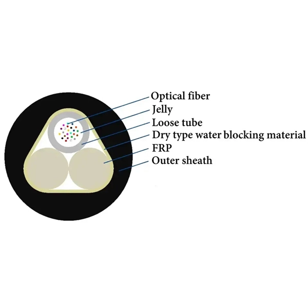
NEC-compliant grounding wire sizing calculator tool. Please enter a valid service size between 30 and 2000 amperes. The National Electrical Code (NEC) provides clear guidelines for ground wire sizing through Table 250. 122, but understanding how to apply these requirements correctly can make the difference between a safe installation and a costly code violation. Proper grounding conductor sizing is critical for. Calculate proper grounding wire sizes based on electrical system parameters. By fault current and length — considers potential short-circuit currents and conductor distance. By breaker size — quick lookup based on the installed breaker. NEC Ground Wire Size Chart provides standard wire sizing for grounding conductors in electrical systems. This chart is used to size the ground wire that runs with branch circuits and feeders. The second is the Grounding. AFL AlumaCore OPGW (Optical Ground Wire) is preferred for its central aluminum pipe and color-coded fiber optic buffer tubes which simplify the splicing process while providing optimum fiber protection as well as long term product reliability. Optical Ground Wire (OPGW) is a dual functioning cable.
[PDF]

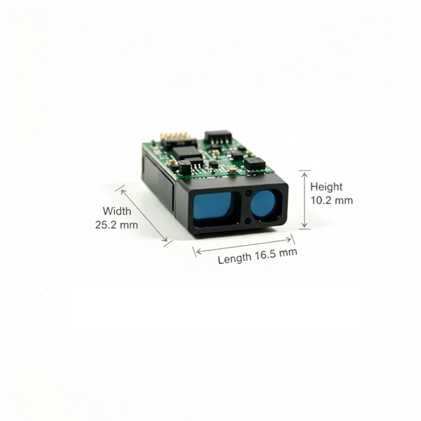
On the US market, a 5. 26 mm 2 (10 AWG) ground wire must be used, and in all other markets a 6 mm 2 must be used. Grounding of the units: Attach a ground wire from one of the threaded studs (A) at the bottom of the housing, to the mounting plate (B). Power from factory ground must be installed by a qualified electrician. Each DISTRIBUTION BOX and controller must be grounded. Whether you're a seasoned pro or just starting out, this comprehensive guide will give you practical. To define the technical specifications for the supply of Fibre Optic Overhead Ground Wire (OPGW) for installation on extra high voltage power lines, under the responsibility of Tasmanian Networks Pty Ltd (hereafter referred to as 'TasNetworks'). This standard applies to all OPGW purchased for. 4. FO-VC2 JOINT USE - VERICAL MIDSPAN CLEARANCES 48. FO-GB GROUNDING AND BONDING 49. FO-RI JOINT USE RISER. The requirement includes the design, supply, stringing and splicing of OPGW cable on 400KV, 220KV & 132KV Transmission Towers. This specification defines the design, material, performance and test requirements for fibre optic cable to support the fibre optic telecommunication needs. The work. IPMENT, STRUCTURES, ETC. IN ELECTRICAL STATIONS INCLUDING TRANSMISSION AND DISTRIBUTION SUBSTAT GR THAN 8 FT FROM THE FENCE. THE FENCE SHALL BE GROUNDED SEPARATELY FROM THE GRID UNLESS OTHERWISE NOTED ON THE A PROPRIATE PROJECT DRAWING. FOR FENC G O OUTSIDE CLEARANCE SPACING. SEE APPLICATION.
[PDF]
If an EGC cable is installed in or on a cable tray, it should be bonded to each or alternate cable tray sections via grounding clamps (this is not required by the NEC® but it is a desirable practice). Cable tray may be used as the Equipment Grounding Conductor (EGC) in any installation where qualified persons will service the installed cable tray system. There is no restriction as to where the cable tray system is installed. The metal in cable trays may be used as the EGC as per the limitations. Cable tray grounding wire is the safety connection that links your electrical system's cable tray to the ground. This provides a safe path for any stray electrical currents to flow safely into the earth, avoiding damage to your equipment and reducing the risk of electric shocks. Grounding points and conductor locations must be determined. The design must comply with relevant regulations and standards.
[PDF]
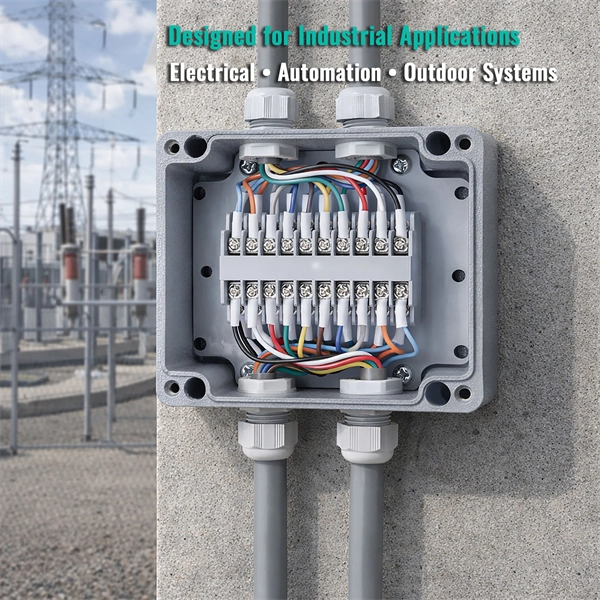
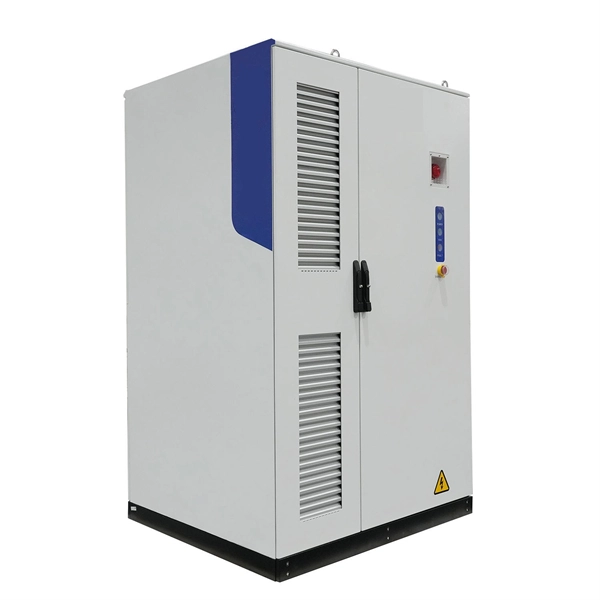
Follow height rules when installing a distribution box. Wall-mounted boxes should be 4. Outdoor boxes need to be at least 3 feet above the ground. This keeps them safe from water and dirt. The proper installation of a distribution box involves placing it at the right height to ensure safety and convenience. 7 meters) high makes it easily accessible without the need to bend or stretch excessively. This height also safeguards the box from potential. Household distribution boxes can be installed on the ground or on the wall. When flused installed in the wall, the bottom is 1. Covers wiring, placement, standards, and expert tips for a compliant setup. It takes the incoming power and safely distributes it to different circuits throughout your building. The National Electrical Code (NEC) provides comprehensive safety standards for electrical installations, including requirements for electrical panels (main service panels and subpanels or breaker box). One outdoor receptacle is required at the front and rear of the house and in the perimeter of each deck, porch, patio, or balcony that is connected to the home. To run electrical. According to the "Code for Acceptance of Construction Quality of Building Electrical Engineering" GB50303-2002, the vertical distance between the bottom surface of the fixed stainless steel enclosure ip67 and the ground should be greater than 1. 3 meters and less than 1. The bottom surface.
[PDF]
When designing a cable tray wiring system, the designer should evaluate the National Electrical Code's (NEC) Equipment Grounding Conductor (EGC) options that are applicable for the project. Use the cable tray as the EGC. The metal in cable trays may be used as the EGC as per the limitations. Cable tray grounding wire is the safety connection that links your electrical system's cable tray to the ground. This provides a safe path for any stray electrical currents to flow safely into the earth, avoiding damage to your equipment and reducing the risk of electric shocks. It involves connecting cable trays to the facility's grounding system, providing a low-impedance path for fault currents and protecting personnel.
[PDF]

The process involves a combination of national infrastructure, local engineering, and property-level setup. In this guide, we'll break down the fiber installation process from start to. This guide walks you through the complete fiber installation process, from checking availability to optimizing your Wi-Fi network performance. Fiber transmits data using light signals through glass strands, delivering faster speeds and lower latency than cable or DSL connections that rely on. In this article we'll break down how fiber internet is installed - from the network fiber drop outside your house to the in-home setup with your router and gateway - and what you should expect at each stage. Fiber optic internet is generally installed in the following 5 steps, which we'll dive. Want lightning-fast internet at home? Fiber optic installation is the way to go! It's super reliable and perfect for streaming, gaming, or using multiple devices. This guide breaks down the process in easy steps so you know what to expect. BCS Consultants, a trusted fiber optic installation company based in California, provides end-to-end fiber optic services, including expert planning. However, setting up a fiber optic connection to your router can seem daunting if you're unfamiliar with the process. In this guide, we'll walk you through how to connect a fiber optic cable to a router safely and efficiently. Why Use Fiber Optic Internet? Before diving into the setup, let's quickly.
[PDF]
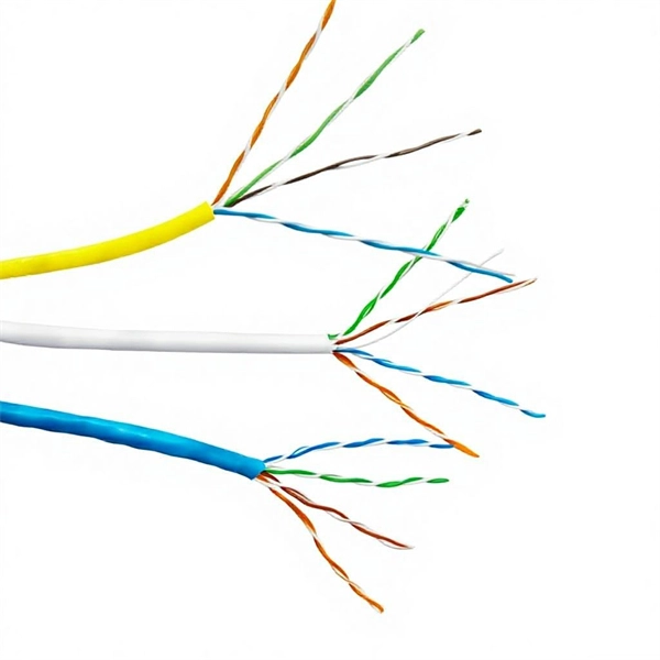
The process involves a combination of national infrastructure, local engineering, and property-level setup. In this guide, we'll break down the fiber installation process from start to finish and explain key components such as fiber cabinets, flower pods, ducting, and ONT. Our fiber optic installation process covers everything from planning and preparation to termination and testing. But how does it work? Keep reading to find out. What Is Fiber Optic. This fiber optic installation method statement covers the termination of fiber optic cables with patch panel, network distribution cabinet NDC and door junction box but can be applicable for any kind of network installations. Roles and Responsibilities: The electrical manager shall be responsible. Setting up a fiber optic network requires careful planning and execution. This guide provides a step-by-step overview of the installation process, ensuring a smooth transition from traditional cabling systems. Introduction Installing a fiber optic network can seem daunting, but with the right. This beginner-friendly guide will walk you through the step-by-step process of fiber optic cable installation for each method, highlighting best practices, tools, and considerations. Unlike traditional copper wiring, fiber optics installation provides superior bandwidth, faster speeds, and resistance to electromagnetic interference.
[PDF]

Protect border security against illegal crossings, smuggling and unauthorized intrusions with a 24/7, real-time fiber optic perimeter intrusion detection system (PIDS) that can be mounted on fences, buried underground or deployed in a top-of-wall configuration. AP Sensing's Distributed Acoustic Sensing (DAS) technology delivers real-time perimeter and border protection by transforming standard optical fibers into dense acoustic sensor arrays. Acting as a Perimeter Intrusion Detection System (PIDS), DAS provides continuous, highly precise monitoring. It. The basic idea of fiber sensing technology is to utilize optical fibers as distributed optical sensors to detect and monitor changes in temperature and strain in a fiber or detect vibrations (sound/acoustics) in the environment around a fiber. It can also be used to protect data conduits and buried pipelines. Advanced adaptive signal processing along with certified SMS/VMS integration options ensure the. Perimeter Intrusion Detection Systems are systems used in an external environment to detect the presence of an intruder attempting to breach a perimeter. Modern security systems, driven by. Technica Fiber Tech's Fence Rakshak is a Fiber Optic based Perimeter Intrusion Detection System (PIDS) that can make organisations fully secure by identifying intruders and blocking such access. Our turnkey solutions can identify any unauthorized intrusions, evaluate the situation, and track.
[PDF]
This guide summarizes field-proven rules for AI/AO/DI/DO wiring, shows how to choose between NO/NC contacts under the fail-safe principle, and explains how to decode typical cable schedule entries. Instrument installation with the associated cable installation/electrical signal and control wiring should be carried out by skilled personnel who are acquainted with the safety requirements and regulations for the plant site for that specific project. Generally instrument cabling is usually run in. Few factors are to be considered or taken care of while wiring a field instrument to control panel. Based on noise susceptibility limits (NSL) according to IEEE 815 standard, various field instrument signals are classified as below. Noise Susceptibility Limit Grounding of the signal cable Type of cable Cable Terminations Based on noise susceptibility limits (NSL). Note how the hoop-shaped “jumper” wires are all cut to (nearly) the same length, and how each of the wire labels is oriented such that the printing is easy to read: This next photograph shows a great way to terminate multi-conductor signal cable to terminal blocks. Each of the pairs was twisted. A well-designed and properly installed instrument junction box is crucial for the efficient operation and maintenance of electrical systems. Level 1: High to medium susceptibility Level 2: Low susceptibility.
[PDF]

This video shows real on-site footage of electrical installation, demonstrating safe and standardized wiring methods used by professionals. The National Electrical Code (NEC) Section 700. 10 provides critical guidelines for the wiring of emergency systems. These systems ensure continued operation during power outages, protecting lives and maintaining functionality in key buildings. This guide breaks down the essential requirements of. Emergency system circuits supply power to critical life safety loads such as emergency lighting, fire alarm systems, fire pumps, smoke control systems, and essential communication and control circuits. Correct wiring design for emergency system circuits is essential to maintain power integrity. The general rule in 700. 10 (B) is to keep wiring from an emergency source or emergency source distribution overcurrent device to the emergency loads entirely separate from all other wiring and equipment, unless otherwise permitted in 700. 10 (B) (1) through (5). 12) of the interruption of the normal electrical supply.
[PDF]
This video shows real on-site footage of electrical installation, demonstrating safe and standardized wiring methods used by professionals. Covers wiring, placement, standards, and expert tips for a compliant setup. A distribution box is the heart of any electrical system. It takes the incoming power and safely distributes it to different circuits throughout your building. In this video, we'll walk you through the process of wiring a home distribution box with a detailed connection diagram. Whether you're an electrician or a DIY enthusiast, this guide will help you understand the basics of home electrical distribution. It has three categories: residential, commercial and industrial electrical distribution boxes, all of which play important roles in their respective electrical. This guide aims to provide a comprehensive overview of double wide mobile home electrical wiring diagrams, covering everything from the main service panel to individual circuits. This panel is. Box installation: Make sure that Distribution box has been correctly installed and fixed. Material preparation: Prepare the required circuit breakers, wires, wiring ties and other materials, and ensure that they meet the design drawings and installation requirements. Location determination:.
[PDF]
This video shows real on-site footage of electrical installation, demonstrating safe and standardized wiring methods used by professionals. more Learn how to wire a distribution box step by step! This video shows real on-site footage of. A distribution box is the heart of any electrical system. It takes the incoming power and safely distributes it to different circuits throughout your building. Whether in a home or an industrial facility, this box keeps your electrical setup organized, functional, and efficient. However, the key to. In this video, we'll walk you through the process of wiring a home distribution box with a detailed connection diagram. What is Distribution Board? Distribution board. An electrical panel box, also known as a breaker box or a distribution board, is a crucial component of any electrical system. It serves as a central hub for distributing electricity throughout a building, ensuring that power is delivered safely and efficiently to all the required locations. A distribution board (also known as a service panel or breaker box) is a centralized collection of circuit breakers, fuses, and/or relays used to control and protect the wiring in a home. The diagram. Electrical wiring powers everything in your home, from lights and outlets to major appliances. We'll break down the key parts of a home.
[PDF]