This list was initially developed as part of AfTerFibre, a project to map terrestrial fibre optic cable projects in Africa. The project was sponsored by and, on completion, will be hosted by the UbuntuNet Alliance. All information gathered by the project will be publicly available under an open license.
[PDF]

An Optical Distribution Frame (ODF) is a dedicated unit designed to organize, terminate, and interconnect fiber optic cables. It brings together fiber splicing, patching, and cable routing in a single structure, while shielding sensitive connectors and splices from mechanical. In the complex architecture of fiber optic networks, the Optical Distribution Frame (ODF) serves as the linchpin for organizing, protecting, and distributing optical signals. Whether in data centers, telecom central offices, or enterprise network rooms, ODFs enable efficient fiber management. This complete guide explores everything you need to know about ODFs — from their structure, types, and key components, to installation best practices and modern design trends. They provide efficient fiber optic management, connectivity, and protection. ODF, also known as optical distribution frame or fiber optic patch panel, is a critical device used in optical communication for managing and distributing optical fibers. As data centers, enterprises, telecom operators, and smart-building infrastructures deploy increasingly dense fiber links, ODFs provide the structured. An ODF is a central hub in fiber optic networks, crucial for managing and organizing the variety of fiber-optic cables and connections entering a facility such as a telco central office (CO).
[PDF]

One SFP module is inserted into the switch's SFP port, and another module is inserted into the SFP port of the target device, facilitating data transmission through the fiber optic cable. SFP ports are small hot-pluggable module interfaces typically used for connecting fiber optics or copper cables. They support various transmission rates and distances, including 1G, 10G, and higher speeds. SFP modules can be selected based on the requirements, whether it's single-mode fiber for. An SFP port is a physically small slot in a networking device that accepts an SFP module insert. Most modern networking devices, such as Ethernet switches, servers, routers, network interface cards, and fiber media converters, generally have two or more built-in SFP ports. You may connect different. In plain terms, an SFP port on a gigabit switch is the little plug-in hole that gives the switch physical flexibility — the ability to use fiber one minute and copper the next without buying a different switch. Unlike fixed RJ45 copper ports, SFP ports support both fiber and copper modules, enabling far longer distances, greater flexibility, and improved scalability in enterprise. First, to connect SFP modules with fiber optic cables, ensure that the module type matches the line, as there are different modules for single-mode and multimode fiber. Next, insert the module firmly and securely into the SFP port, then attach the cable to the module using the connector. Switches with SFP ports can.
[PDF]
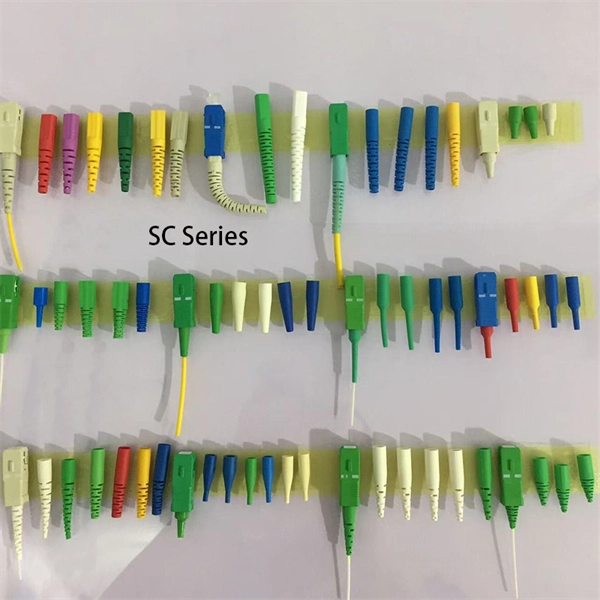
This video goes over common types of connectors, their respective adapters, and how to properly connect and disconnect them. more Are you interested in seeing how fiber optic connectors get. Unplugging a fiber jack, also known as a fiber optic connector, is a delicate process that requires attention to detail and proper handling to ensure the integrity of the fiber optic cables and connectors. Fiber optics are used in a variety of applications, including telecommunications, internet. If you're wondering how to remove fiber optic cable from connectors, there are a few different ways to do it. You need to know which connector is the correct one for the cable and what kind of wire it's made of. You can also use shears or wire cutters to cut through the connector. This article. Fiber optic connectors are essential components in fiber optic networks, providing a reliable connection between cables and equipment. Removing these connectors requires care to avoid damaging the delicate fibers or the connector itself. To connect a fiber optic cable to SFP optical module, first ensure the SFP is fully inserted into the network port until it "clicks", then remove the dust caps from both the SFP and the LC fiber optic connector.
[PDF]
The ProCurve Switch 2800 series consists of two switches: the 24-port ProCurve Switch 2824 with 20 10/100/1000 ports, and the 48-port ProCurve Switch 2848 with 44 10/100/1000 ports. In addition, each switch has 4 dual-personality ports for RJ-45 10/100/1000 or mini-GBIC fiber. Manuals and User Guides for HP ProCurve 2848. We have 3 HP ProCurve 2848 manuals available for free PDF download: Function Manual, Install Manual, Datasheet Hp ProCurve 2848 Pdf User Manuals. View online or download Hp ProCurve 2848 Function Manual, Install Manual, Datasheet. I am going to link the following 3 switches, HP Aruba 2920-48 POE, 2510-48 and 2848, by double fibre optic cables (through the miniGBIC slots) so double link from the 2920 to the 2510 and the a double link to the 2848. You can examine HP ProCurve 2848 Manuals and User Guides in PDF.
[PDF]

How to Install a Fibre Connector into a Patch Panel (Easy fibre optic connector installation) How to Install a Fibre Connector into a Fibre Optic Patch Panel. How do you install fibre optic connectors?. Connecting a fiber patch panel to a switch is a critical step in setting up a fiber optic network. There are different types of connectors. In today's high-performance networks, fiber optic patch cables are the lifelines that ensure smooth data flow across switches, servers, and routers. Even the most advanced optical transceivers can only perform at their peak when paired with properly installed, clean, and precisely managed fiber. Choose an SFP module based on the fiber optic cabling that will be connected to the network switches. SFP transceiver modules almost always require two fiber optic cable strands. A Fiber Patch cord connects two devices. You plug it into a switch, router, or patch panel. It's ready to use out of the box. A pigtail is for splicing. You fuse it to a. With a railroad switch (patch panel), the train (data) can travel from A to B, C and even more destinations, otherwise it can only go from A to B, or C to D. This article, What Is a Patch Panel Used for?, has explained it thoroughly.
[PDF]
Optical Fiber Cable & Accessories Price in Nepal, Kathmandu. Buy with best and reasonable price @ ITShop Nepal. Nepal - Shop for Best Online at Daraz. np Wide Variety of fiber optic box. Great Prices, Even Better Service. Made of brand new materials, sturdy and durable, resistant to impact, corrosion, sealed and waterproof, safe and worry free Engineered for outdoor use, this junction box showcases a robust waterproof design, safeguarding critical fiber optic connections against harsh weather and ensuring reliable. Optical Fiber Cable & Accessories Price in Nepal, Kathmandu. SÜRGÜLÜ PATCHPANEL SC UPC DUBLEX 24XADAPTÖR 48XPIGTAIL RAL7035 1u 19” MEK. GJS-901-2 fiber optic splice closures (FOSC) are used to distribute, splice, and store the outdoor optical cables which enter and exit from the ends of the closure. There are two connection ways: direct connection and splitting connection. Applicable to situations such as overhead, man-well of. vianet: Vianet Communication Ltd. is a leading Internet & TV service provider in Nepal. Since 24 years, Vianet Communication has always remained at the forefront, providing reliable and affordable Fiber Broadband Internet Services.
[PDF]
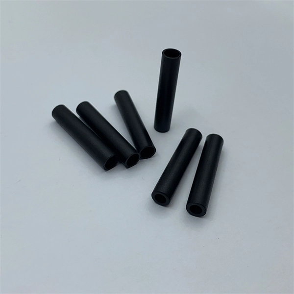
Yes. Standard scissors and a ruler will be adequate in most cases, unless you require an exact length of tubing, in which case use a more precise measuring tool. For thicker tubing you may require wire cutt.
[PDF]

When switching to fiber internet, many users wonder if they're able to use their own router instead of the one provided by their internet service provider (ISP). In this guide, we'll explain router compatibility, setup steps and whether upgrading your router is necessary to maximize fiber speeds. Selecting a single router can be challenging, as there are most likely many that fit the requirements you want. We've done the research for you and put together this in-depth guide that lists multiple options, their details, reviews, and pros and cons. This should help you make an informed decision. Unlike cable internet, fiber connections do not require a cable modem. Instead, you simply plug a wireless router into the ONT provided by your ISP, set it up, and start using the internet. But if you're unsure which router to get, you're in the right place. Instead of using your old router, a high-performance Wi-Fi router designed for fiber optic internet will ensure you seamless streaming, online gaming, and remote work all. This article provides a comprehensive review and buying guide designed to assist in identifying the best routers for fiber internet. We will explore key performance metrics, essential features such as Wi-Fi standards and port configurations, and examine a range of router models optimized for fiber. Yes, you can often use your existing router with fiber optic internet, but there are crucial considerations. This guide will break down everything you.
[PDF]
Choosing the right fiber optic cable factory is vital to ensuring the performance, longevity, and reliability of your network. This article provides a guide from various dimensions on how to choose the right suppliers and manufacturers, along with a detailed. Selecting the right fiber optic cable manufacturer directly impacts your network's reliability, performance, and total cost of ownership. With the global fiber optic cable market valued at $13. 92 billion and growing at 10. The industry landscape features both global. This article highlights leading fiber optic cable manufacturers in the United States, renowned for their high-quality products and innovative solutions. For procurement managers and network engineers, the challenge is balancing performance, budget, and lead times. But if you want to find the best one, it's a bit difficult. Don't worry, Gcabling will help you. Gcabling, as a leading optical cable manufacturer that can. Based on 2025 rankings from industry sources like Owire and TSCables, the top manufacturers are evaluated on market share, innovation, and global reach. This list incorporates leading players, including Dekam-Fiber, Corning, Prysmian, and CommMesh, which stand out for their contributions to.
[PDF]
BiDi SFP+ changes the geometry: each module uses a single fiber pair directionally separated by wavelength, so you can run one strand where you previously needed two. One of the most common decisions network engineers face is selecting between single fiber SFP and dual fiber SFP modules. This comprehensive guide explores the differences between single and dual fiber SFPs, their respective benefits, limitations, and use cases—helping you make an informed choice. A single fiber SFP, also known as a BiDi SFP, is designed precisely for this purpose—enabling bidirectional data transmission over a single strand of optical fiber. Unlike traditional SFP transceivers that require two fibers—one for transmitting and one for receiving—a single fiber SFP uses. SFP (Small Form-factor Pluggable) is a compact, hot-pluggable network interface module used to connect network devices (switches, routers, firewalls) to fiber optic or copper cables. An SFP interface on networking hardware is a modular slot for a media-specific transceiver, such as for a fiber-optic cable or a copper. Both transmitting and receiving need one optical fiber to connect. Simplex SFP modules, also known as BIDI transceiver, employs a unidirectional transmission mechanism and have only one port. In practice, that means fewer splice points, smaller patch panels, and less conduit congestion—especially in retrofit buildings.
[PDF]

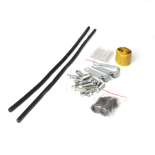
It is an interference type damper designed to attenuate the energy of cable vibration and restrain cable vibration amplitude by impacting with its damping section, so as to protect cables. Spiral vibration dampers have a helically-formed damping section sized for interplay of damper and cable to provide the action/reaction motion that opposed the natural vibration wave. The shock absorber damper is an interference type damper to attenuate vibration amplitude by impact with its damping section and especially designed for ADSS cable and OPGW cable of diameter less than. Spiral Vibration Dampers using its anti-vibration part to produce antihunt action to the wind vibration, consuming the vibration energy that produced by the cable running under the action of laminar wind,to prevent the destruction of gold tool and fiber optic cable, which mainly used for ADSS. Shop DigiKey's large in-stock selection of Spiral Wrap, Expandable Sleeving. View inventory, pricing and order now for same day shipping!.
[PDF]
Search below to explore initial fiber availability in your area. Login to your CarrierFinder account for detailed insights and full access to carrier data. Enter your address and discover fiber and broadband internet providers. We'll show you which fiber networks and providers serve your address and the best plans. Fiber broadband, or fiber internet, is powered by fiber optic cables and has the potential to transmit data at much higher speeds than DSL or cable internet. How do I know if I have AT&T home internet availability at my address? AT&T home internet availability depends on your address. This means. By integrating Frontier's complementary pure-play fiber network with Verizon's industry-leading Fios and mobility assets, the company now has an expanded reach of almost 30 million fiber passings across 31 states and Washington, D. With the greater availability of premium home internet and. Fiber internet is a broadband connection that runs on light signals from fiber-optic cabling, delivering multi-gig upload and download speeds. It's the fastest and most reliable internet you can get, and most plans come with straightforward pricing and included Wi-Fi equipment. The map will be updated continuously to improve its accuracy through a combination of FCC verification efforts, new data from Internet.
[PDF]