
Managing optical attenuation helps keep your signal safe. Clean your optical connectors so you do not lose. Optical Signal Attenuation is the single greatest factor limiting the distance and performance of your network. Understanding it is crucial for anyone involved in data centers, telecommunications, or enterprise networking. This guide will demystify signal loss, explore its causes, and show you how. In high-speed environments, where the optical link budget is measured in fractions of a decibel, diagnosing and eliminating unexpected loss is the network engineer's most critical task. This field guide provides a systematic, step-by-step approach to troubleshooting and resolving the most common. Signal loss in Fiber Optic networks can make data slow. It can also break your connection. You should fix it fast to get speed and stability back. > You can solve this with simple steps. Signal Degradation (Loss of Light) When the signal quality degrades, it could be a sign of attenuation or excessive loss in the system. The signal might become weaker, resulting in slower speeds or dropped connections. -. Fiber optic networks are celebrated for their speed and reliability, but even the best systems can encounter problems. When issues like signal loss, slow speeds, or intermittent connectivity arise, systematic troubleshooting is key. Things like impurities in the fiber core and reflections at the core-cladding edge cause this drop.
[PDF]

This document provides a comprehensive framework for the classification, characteristics, and operational parameters of Multi-Degree Reconfigurable Optical Add/Drop Multiplexers (MD-ROADMs), including two-degree ROADMs. com 2 Telecom service providers are adapting their optical backbone networks to meet the demands of cloud networking and relentless video- and mobile-data traffic growth. Combined with a move to ultrahigh-capacity. What is ROADM? ROADM (Reconfigurable Optical Add-Drop Multiplexer) is a key component of optical transport networks (OTN / DWDM systems). It enables adding (Add), dropping (Drop), or passing (Pass) optical channels remotely and flexibly without converting optical signals to electrical signals. PacketLight's PL-1000RO/GRO 4/8/32-degree CDC-F ROADM offers functionality based on advanced next generation wavelength-selective switch (WSS) technology. It allows for flexible and dynamic routing of optical signals by adding (inserting), dropping (extracting), and passing through (routing) specific. Optical Add-Drop Multiplexers (OADMs) are essential components in Wavelength Division Multiplexing (WDM) networks, enabling the selective addition and removal of specific wavelengths within an optical fiber to enhance bandwidth efficiency. With ongoing advancements, OADMs have evolved from FOADMs.
[PDF]

This paper will review the development of fiber-optic high-temperature sensors over the last 30 years, presenting their design and fabrication methods according to sensing type and typical temperature measurement performance. The full paper consists of eight sections. Fiber-optic high-temperature sensors are gradually replacing traditional electronic sensors due to their small size, resistance to electromagnetic interference, remote detection, multiplexing, and distributed measurement advantages. This paper reviews the sensing principle, structural design, and. Luna's Optical Backscatter Reflectometer (OBR) products are based on OFDR and provide a level of detail and precision not available with the prevailing fiber optic diagnostic tool - the optical time domain reflectometer (OTDR). OBR systems map out loss along a single-mode fiber (SMF) or multi-mode. breadth and most comprehensive solutions for optical communications test products to be found in one place. Corning's High Temperature Fibers are designed for applications requiring improved fatigue resistance, high usable strength, and excellent resistance to higher temperatures and hydrogen permeation. Thus, wireless communication -situ processing of data would combined with in significantly improve the ability to include sensors into high temperature systems and thus lead toward more intelligent engine systems. NASA Glenn Research Center (GRC) is presently lea, communication systems,ding the.
[PDF]

Telescopic mast system with advanced vibration-dampening technology to minimize jitter and ensure stable communication and data transmission, even in the most demanding terrain and vehicle movements. Fireco designs and manufactures the most comprehensive line of standard and custom telescopic masts using high quality materials with industry leading engineering and quality testing practices to provide our customers with the world's best mobile masts. Will-Burt's telescopic masts and tower systems provide intelligent. Telescopic mast systems play a critical role in modern field operations—enabling elevation of cameras, antennas, lights, sensors, and communication gear in demanding environments. Whether for surveillance, broadcasting, defense, or emergency response, choosing the right mast system ensures reliable. Floatograph, along with its utility industry partner, Eversource Energy, developed the Rapid Pole® – Temporary Power Pole system to reduce customer downtime, allowing crews to re-energize a circuit in as little as 20 minutes. Floatograph's masts come in height options from 10 to 100 feet, and are. Advanced telescopic mast solutions designed for versatility in the field, providing crucial support for on-the-move (OTM) missions. Erecting the Telescoping Mast is made by simply connecting guys and brackets to the attached unique heavy duty rolled edge guy rings and clamps, extend the sections, insert the locking cotter pins, rotating the tubes to.
[PDF]
The zero-buoyancy rov cable was born as a power connection and control of underwater robot equipment, as well as signal transmission and feedback link cable applications. The zero-buoyancy cable has been tested by the market and practice due to its excellent. The global underwater zero buoyancy cable market is experiencing robust growth, driven by the expanding offshore energy sector, increasing demand for subsea infrastructure development, and advancements in underwater communication technologies. Linden Photonics is renowned for its innovative fiber-optic solutions, specifically designed for Remote Operated Vehicles (ROVs). These ROV tethers are crucial in underwater applications, offering high performance, durability, and reliability in challenging environments. For use with ROV's (Remote.. Customizable neutral buoyancy fiber optic power cable for ROVs and underwater drones. High‑performance hybrid design combining power and data in one composite cable. Engineered for seawater resistance, flexibility and subsea reliability. Suitable for inspection systems, subsea cameras and. At Invocean, we understand the increasing demands and the critical nature of Remotely Operated Vehicles (ROVs) in various industries such as underwater construction, surveillance, salvage, and scientific research. To support these high-performance tasks, ROVs and Micro-ROV's require reliable.
[PDF]

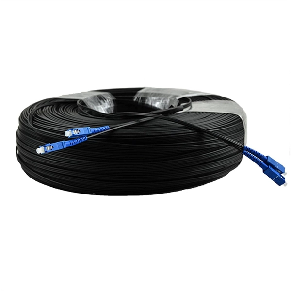
This procedure provides general information for installing all Corning Optical Communications Solo® ADSS All-Dielectric Self-Supporting fiber optic cables from 2-288 fibers. This document provides installation instructions for the Cisco Coarse Wave Division Multiplexer (CWDM) passive optical system. The CWDM passive optical system product numbers are listed in Table 1. Copyright © 2004–2005 Cisco Systems, Inc. Each installation will be influenced by local conditions. The reader should be experienced in aerial fiber optic cable. ADSS Cables (All-Dielectric Self-Supporting Cables) are a specialized type of fiber optic cable designed for aerial installation without metallic components. As someone who has worked on numerous ADSS projects at Bright Power Co. Since there are numerous practices which may be utilized, Prysmian has tested and determined that the practices described herein are effective and efficient. They are adopted widely because they are made of fully dielectrics, are relatively lightweight, and can be installed even without conducting.
[PDF]

In this paper, various operational factors affecting 100G transmission over G. D fiber-cables are discussed to make the right fiber selection for the long-haul network. Selecting appropriate G. 652 fibre was originally optimized for use in the 1310 nm wavelength region but can also be used in the 1550 nm region. This is the latest revision of a Recommendation that was first created in 1984 and deals with some relatively minor modifications. a number of concatenated cable. G. 92% of. Fiber optic cables are the ultimate technology used in data transfer using light waves. They are classified based on wavelength band, core/cladding size, application, and compliance with international standards such as IEC, ITU-T, and TIE/EIA. In the next sections, the real artwork is putting on. This guide explains the most important ITU-T G. 655—to help you make an informed decision for your project, whether it's a long-haul backbone or a final FTTH drop. In the world of fiber optics, not all glass is created equal. The core of every cable—the optical. Because GPON and XGS-PON are deployed in diverse environments, fiber-containing components such as PLC splitters must be evaluated not only by their standard parameters but also by their sensitivity to bending loss, which is critical for maintaining stable optical transmission. The ITU-T defines.
[PDF]
Based on analysis on the dispersion of the optical system of a MEMS-based VOA, we provide a method to reduce the WDL significantly with minor revision on the end-face angle of the collimating lens. 📦 For purchasing, use the RP Photonics Buyer's Guide for variable optical attenuators. It provides an expert-curated supplier directory, buyer-focused technical background information, and structured selection criteria to support professional procurement decisions. Variable optical attenuators are. An optical attenuator, or fiber optic attenuator, is a device used to reduce the power level of an optical signal, either in free space or in an optical fiber. The basic types of optical attenuators are fixed, step-wise variable, and continuously variable. Optical attenuators are commonly used in. Applications in broadband optical fiber communication system need variable optical attenuators (VOAs) with low wavelength-dependent loss (WDL). What Are Fiber Optic Attenuators? Fiber optic attenuators, also called optical attenuators, are passive. Optical attenuators are categorized based on their attenuation mechanism and adjustability: Fixed Optical Attenuators: These attenuators reduce the signal power by a predetermined value and are used in applications where a constant level of attenuation is required. It works by dissipating a portion of the optical power passing through it, thereby lowering the overall power level. Fiber optic attenuators.
[PDF]
An optical fiber is a cylindrical ( waveguide) that transmits light along its axis through the process of total internal reflection. The fiber consists of a core surrounded by a layer, both of which are made of materials. To confine the optical signal in the core, the of the core must be greater than that of the cladding. The boundary between the core and cladding m.
[PDF]
In today's data-driven world, high-speed optical modules (e., 100G/400G/800G) are the backbone of modern networks, enabling ultra-low latency and massive bandwidth for data centers, telecom, and enterprise applications. However, their performance hinges on proper deployment. nd Latency variation are very important in applications requiring accurate timing (e (PAM-4 or Coherent), require complex digital signal processors (DSPs) in optic itional EEPROM data content for propagation del ss C. 2” pluggable : 2% of the cTE budget ITU-T G. 2 allocated for Class C A. 20”. This article helps trading engineers and network architects select an ultra low latency SFP that fits 10G/1G optics needs while minimizing added propagation and serialization delay. A solution for accurately measuring the Latency of PAM4 optical modules is required. Potential source of time error in complex digital parts of pluggables. Higher bit rates (50 Gb/s and higher) and. Transceiver latency is a key spec in enterprise fiber optic networks especially in financial institutions. It is the one of the few variables that can be optimized since fiber path delay is fixed. However, their performance hinges on proper deployment and maintenance.
[PDF]
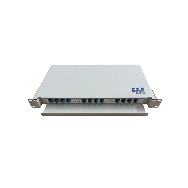
The information contained in this manual should serve as a guide to proper handling, installing, testing, and for troubleshooting problems with fiber optic cables. Optical fibers require special care during installation to ensure reliable operation. FIBER OPTIC CROSS CONNECTION CABINET 144, 288 AND 576 FIBER. Open the cabinet base cover, fix the cabinet on the Cement base. (Fig 1) PLEASE READ THESE INSTRUCTIONS CAREFULLY. Keeping this page as a placeholder for now. Have any questions? Talk with us directly using LiveChat. 0 SCOPE Fiber optic cross connect cabinet is an outdoor optical equipment that is especially designed for outdoor optical nodes in access network. WTC144 ACCOMMODATES ALL CROSS CONNECT FUNCTIONS (SPLICING, TERMINATION, AND INTERCONNECTION) FOR OUTSIDE PLANT, BACKBONE, AND BUILDING CABLES. WTC144 CABINETS CAN BE ORDERED EMPTY, LOADED, OR CUSTOM CONFIGURED TO YOUR PARTICULAR SPECIFICATIONS.
[PDF]
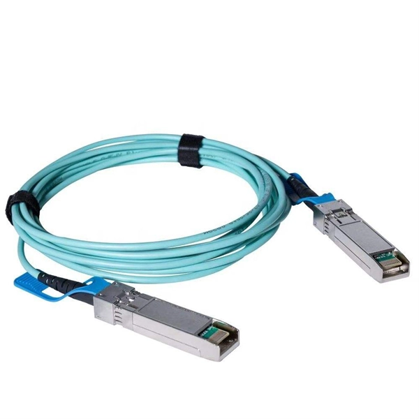
BiDi SFP+ changes the geometry: each module uses a single fiber pair directionally separated by wavelength, so you can run one strand where you previously needed two. One of the most common decisions network engineers face is selecting between single fiber SFP and dual fiber SFP modules. This comprehensive guide explores the differences between single and dual fiber SFPs, their respective benefits, limitations, and use cases—helping you make an informed choice. A single fiber SFP, also known as a BiDi SFP, is designed precisely for this purpose—enabling bidirectional data transmission over a single strand of optical fiber. Unlike traditional SFP transceivers that require two fibers—one for transmitting and one for receiving—a single fiber SFP uses. SFP (Small Form-factor Pluggable) is a compact, hot-pluggable network interface module used to connect network devices (switches, routers, firewalls) to fiber optic or copper cables. An SFP interface on networking hardware is a modular slot for a media-specific transceiver, such as for a fiber-optic cable or a copper. Both transmitting and receiving need one optical fiber to connect. Simplex SFP modules, also known as BIDI transceiver, employs a unidirectional transmission mechanism and have only one port. In practice, that means fewer splice points, smaller patch panels, and less conduit congestion—especially in retrofit buildings.
[PDF]
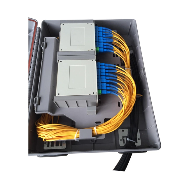
Optical cable junction boxes play a crucial role in connecting and protecting optical fibers, directly influencing the quality and lifespan of optical cable routes. Optical cable splice boxes protect the splicing parts of optical fibers from various hazards, such as water seepage due to adverse. Optical cable junction boxes play a crucial role in managing and organizing fiber optic networks. It serves as a termination point for fiber optic cables, providing protection and distribution of the optical fibers while ensuring efficient signal transmission. Utilizing an optical junction box can significantly enhance your. Optical cable splice box is a popular name, its scientific name is optical cable splicing box, also known as optical cable splicing package, optical cable splicing package and gun barrel. These boxes are designed to house and protect fiber optic splices and terminations, ensuring that the delicate fibers are safeguarded from.
[PDF]


