Poland's high voltage oil insulated switchgear market is estimated at USD 145–175 million in 2026, with a compound annual growth rate of 3. 5% through 2035, driven primarily by grid modernization and renewable energy integration. Successful go‑live of day-ahead and intraday capacit. informs that under the Single Day-Ahead Marke. Due to changes in information requirements for the electricity market and Polish Power System Operation a new website containing system data has been launched. Transmission substations account for approximately 55–60% of. The electricity transmission network in Poland is managed by Polskie Sieci Elektroenergetyczne SA (PSE), which is the sole transmission system operator (TSO) in the country. The entire power system in Poland and throughout Europe (excluding the frequency of railway electric traction in Germany and. The ANIA Electrical Centre, operating within the structure of ANIA HOLDING, has been providing comprehensive solutions for the distribution of electrical goods for over 30 years. PSE is the owner of Poland's high voltage electricity grid and is responsible for grid. Polenergia Dystrybucja builds and maintains its own power infrastructure across Poland, through which it distributes and sells electricity. Your browser does not support the video tag. Our clients include shopping malls, office buildings, industrial parks, warehouse centers, housing cooperatives.
[PDF]

This section provides an overview for busbars as well as their applications and principles. Here are the top-ranked busbar companies as of May, 2026: 1. Chatsworth. Busbars also known as bus bars, barra electrica, or busbar electrical systems are essential components in modern electrical distribution. Whether used in industrial bus bars, EV charging, renewable energy plants, or building infrastructure, busbars offer compact, efficient, and safe current. High Voltage Busbars are critical components in electrical power systems, designed to conduct high voltage electrical currents efficiently and safely. They are used in substations, switchgear assemblies, and electrical distribution systems to connect different parts of the system and manage the. According to Mordor Intelligence, the busbar market was valued at USD 5. 3 billion in 2023 and is projected to reach USD 7. 5% during the forecast period. What. The global busbar market will expand at a great rate and reach USD 19. 24% between 2023 and 2033. The top companies in busbar market are Siemens AG, Connectivity, Mersen, Schneider Electric, Rogers Corporation, Legrand.
[PDF]

The system cover is off or incorrectly installed. The intrusion switch might be triggered or not working. In this scenario at least one fan or fan assembly (contains two fans) is either damaged (connector, fan blade, fan blade frame), missing or failed. Check the front LCD or system event log to. What do the BMC logs say? Does the server overheat? Are the fans just off because it's not under load? what kind of server do you have, give a spec sheet. Server fans maintain critical airflow to prevent component overheating and system failures. (Adapted from hardware diagnostic methodologies in service docs) 💡 *Pro Tip: Replacing bearings extends fan life by 2-3 years at 20% of new fan cost* (Cost data from “Dell & HPE Server Repair Services. we've got 3 Dell PowerEdge R6615 with an AMD Epyc 9174F in it and the fans are doing something weird. Most of the time they are at 8-9k RPM and fairly quiet. But every minute or 2 they are revving up to full speed (~ 24k) or half speed (~ 13k) and then back down. From failed capacitors to deep grime hiding in your rotor shaft — I show you how to diagnose each fault step-by-step using. Server racks can get hot fast. When the heat isn't managed well, it can slow down your servers, cause shutdowns, or even damage your equipment. Over time, this.
[PDF]
In this article, we will provide a detailed wiring diagram for a radiator electric fan, along with step-by-step instructions on how to install it. The wiring diagram for a radiator electric fan consists of several components, including a relay, a fuse, a temperature switch, and. Your Infinitybox IPM1 Kit makes it easy to control your cooling fan. The MASTERCELL NGX takes the trigger signal from your temperature switch or ECU. It sends a command over the CAN network to the front POWERCELL to turn the cooling fan on and off. The POWERCELL has the switching and fuse. Wiring should only be performed by a trained electrician to prevent injury or death. Install manual disconnect switch inside building adjacent to fan. Route all wires to include drip loops and secure. Drip loop will drain accumulated moisture away from motors, controls, and other electronic. Wiring Harnesses, Electric Fan Controls, Accessories, Grounding, Lighting, Switches, Fuel Injection Harnesses, Wiring Aids and More!. However, the process of installing an electric fan can be overwhelming, especially if you're new to automotive wiring.
[PDF]
This section applies to grounding of transmission and distribution lines and equipment for the purpose of protecting employees. Note to paragraph (a): This section covers. Correct grounding of services depends upon understanding the definition and role of the grounded conductor. The neutral conductor is typically the grounded conductor connected to the system's neutral point, carrying current under normal operation. Grounding electrode conductors must be connected at. Learn the grounding and bonding rules when powering two or more buildings or structures in the same area with a single service. To catch up on Lorenzo Mari's series on National Electrical Code 2023 Basics: Grounding and Bonding, follow these links: NEC's Section 250. Bonding is connecting things together with a conductive path to establish electrical continuity. Both are foundational safety concepts in the NEC, and. NFPA 70: National Electrical Code Article 250 covers the minimum requirements for grounding and bonding and, although the NEC lists requirements to abide by, it should not be taken as a design manual. Some terms and requirements discussed may be true for the European standards, however, the intent.
[PDF]

More specifically, these systems keep tabs on voltage, current, and temperature limits and control the disconnect relay. This allows them to disconnect themselves from the external application in case of malfunction. From a drop of rain to the shining sea, an energy storage system is like the earth's bodies of water (hear us out). In a battery energy storage system (BESS), the energy in the battery cells is like raindrops that combine to form a brook. Made of the combined energy from cells, these brooks combine. Battery energy storage systems (BESSs) investment is expected to grow to $103 billion by 2030. ) Battery systems aren't just designed to serve as local power backups, such as the systems used to power critical facilities (including hospitals and data centers) when the normal. When a 300 MWh battery energy storage system (BESS) in Arizona tripped offline during July's heatwave, operators discovered voltage fluctuations had overwhelmed its protection relays. Could your facility withstand such stress? As global BESS installations surge—projected to reach 1. Protection is necessary when energy and voltages combine from the modules, as well as from the battery racks. Fuses are an efficient. The electrical integration design of a Battery Energy Storage System (BESS) is based on the application scenario and includes various aspects such as DC, high/low voltage distribution, control power distribution, grounding, lightning protection, and safety standards.
[PDF]

The World Bank Group has approved plans to develop Botswana"s first utility-scale battery energy storage system (BESS) with 50MW output and 200MWh storage capacity. The World Bank will support the 4-hour duration BESS via a loan of US$88 million. Botswana has today marked a historic milestone in its energy transformation journey with the groundbreaking ceremony and signing of the Power Purchase Agreement (PPA) for the 500MW Maun Solar Photovoltaic (PV) Plant and 500MWh Battery Energy Storage System (BESS), one of the most ambitious. By 2030, 140MW of BESS will be needed to support the uptake of renewable energy generation. This financial boost will fund the construction of a 100-megawatt solar power plant and support a comprehensive renewable energy program designed to bring. Botswana has received an $88 million loan from the World Bank for its first utility-scale battery energy storage system (BESS). The 50 MW/200 MWh project will allow for the stable integration and management of renewable energy on the nation"s grid. In conclusion, the strategic imperatives. The World Bank has provided Botswana, one of the world's fastest-growing economies, with a loan to finance a 50 MW/200 MWh battery energy storage system, the nation's biggest such project to date.
[PDF]

The proper installation of a distribution box involves placing it at the right height to ensure safety and convenience. 7 meters) high makes it easily accessible without the need to bend or stretch excessively. (1) Elevator driving machines, motor generator sets, controllers, and auxiliary control equipment shall be installed in a room or enclosure set aside for that purpose. This height also safeguards the box from potential. The work space shall be clear and extend from the grade, floor or platform to a height of 6 1 / 2 feet or the height of the equipment, whichever is greater. The electrical equipment itself may have a height that is less than 6 1 / 2 feet, but if it is mounted so the top of the equipment is higher. Overcurrent devices and disconnects must be located in machine or control spaces, be lockable and provide a single means to disconnect ungrounded conductors, with selective coordination for multi-elevator feeders. Conductor and wireway fill, approved flexible traveling cables and secure supports. Choose the right box based on environment (indoor/outdoor), load capacity, and durability. Check for proper IP/NEMA ratings and material quality. Ensure safe placement: install in dry, accessible areas with good ventilation and at appropriate height (typically ~1. Practice good wiring: secure.
[PDF]

The primary problem encountered is signal loss, also known as attenuation. Attenuation can be due to absorption, scattering, or bending losses, affecting the quality and speed of data transmission. Attenuation in fiber optic cables is the reduction in signal strength during. To be able to judge whether a fiber optic cable plant is good, one does a insertion loss test with a light source and power meter and compares that to an estimate of what is a reasonable loss for that cable plant. The estimate, called a "loss budget" is calculated using typical component losses for. F iber optic networks rely on the efficient transmission of light signals to deliver high-speed data over long distances. However, various factors can cause signal degradation, leading to performance issues and reduced network reliability. Fiber optic signal loss, also known as attenuation, occurs. A significant signal loss in the optical fiber can cause unreliable transmission. How can we know the value of losses on the fiber link? Read on, this post will teach you how to calculate the losses in optical fiber and judge the fiber link performance. The uses various types of network cables, including multimode and single-mode fiber-optic cable. It can also break your connection. High attenuation makes your system not work well. You should fix it fast to get speed and stability back. > You can solve this with simple steps.
[PDF]

The OMERIN Group is the world's leading manufacturer of cables for extreme conditions (-190°C to +1400°C). Find here High Temperature Cables, High Temperature Wires manufacturers, suppliers & exporters in India. Ideally for a wire to be classified into this category needs to have a temperature rating of 125 degrees C. The High-Temperature Wires can either be a multiconductor or a single conductor. To find out. Established in 1990, Thermo Cables Limited has evolved into a leading manufacturer of specialty cables, serving diverse industries such as Railways, Navy, Defence, Renewable Energy, Nuclear Power, Process Industries, Oil & Gas, and Power sectors. As part of Thermo Group, we are seamlessly. 'Udeytemp' is a specially developed asbestos free insulation material for high temperature use can be insulated on all types of cables covering a vast variety of applications. and. Jiangsu and Zhejiang provinces specialize in industrial-grade cables, hosting facilities like Jiangsu Plaza Premium Electric Instrument and Zhejiang Teflon Wire & Cable with 5,400–6,200 m² production areas. Guangdong's Shenzhen and Dongguan regions focus on high-volume exports, evidenced by. The list above is filled with wholesale jumper wire suppliers, wholesalers, factories, manufacturers (OEM, ODM & OBM), importers, exporters, agents, and more that are certified and verified by Global Sources.
[PDF]

This paper will review the development of fiber-optic high-temperature sensors over the last 30 years, presenting their design and fabrication methods according to sensing type and typical temperature measurement performance. The full paper consists of eight sections. Fiber-optic high-temperature sensors are gradually replacing traditional electronic sensors due to their small size, resistance to electromagnetic interference, remote detection, multiplexing, and distributed measurement advantages. This paper reviews the sensing principle, structural design, and. Luna's Optical Backscatter Reflectometer (OBR) products are based on OFDR and provide a level of detail and precision not available with the prevailing fiber optic diagnostic tool - the optical time domain reflectometer (OTDR). OBR systems map out loss along a single-mode fiber (SMF) or multi-mode. breadth and most comprehensive solutions for optical communications test products to be found in one place. Corning's High Temperature Fibers are designed for applications requiring improved fatigue resistance, high usable strength, and excellent resistance to higher temperatures and hydrogen permeation. Thus, wireless communication -situ processing of data would combined with in significantly improve the ability to include sensors into high temperature systems and thus lead toward more intelligent engine systems. NASA Glenn Research Center (GRC) is presently lea, communication systems,ding the.
[PDF]
The first step to finding the right KVM switch is taking inventory of what you'll use it with: specifically, the number of computers, monitors, and additional peripherals, such as a keyboard and mouse. Yo.
[PDF]
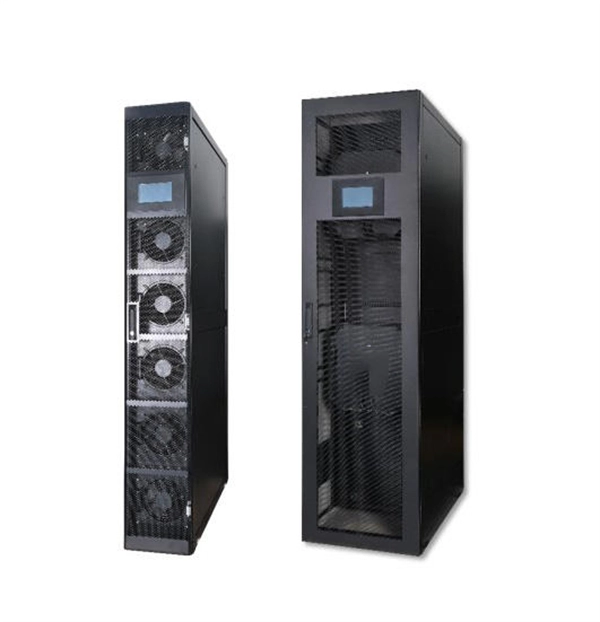
The mounting height of a network rack typically ranges from 24 inches to 84 inches (2 to 7 feet), depending on the equipment and installation requirements. A server rack is more than just a physical frame—it determines how well your rack servers, network switches, PDUs, and storage arrays can be organized, cooled, and maintained. Selecting the right rack size ensures not only compatibility with today's hardware but also room for future expansion. The. Common server rack sizes are 19‑inch width, heights like 42U or 48U, and depths from ~24″ to 48″. Choose size based on equipment type, cooling, space, and future growth. Most IT environments default to 42U, 19-inch width, and 1000–1200 mm depth unless space constraints or special equipment dictate. A rack unit, abbreviated as “U,” is the standard unit of measurement for the height of devices designed for rack mounting. One rack unit equals 1. Important: U describes height only, but a server's real "capabilities" are also determined by chassis depth, internal layout, airflow, rails, power, and expansion (PCIe/risers, NVMe. You'll get precise, vendor-agnostic dimensions for standard server rack sizes—including exact width (19″ internal / 24″ external), height (42U = 73. 5″), depth (24″–48″), and the universal 1U = 1. 75″ rule—plus how to verify usable space, avoid common fitment errors, and select based on equipment.
[PDF]
